KEF KHT 5005 Installation Manual Download Page 2

FOR UK:

The mains lead is terminated with a moulded three pin plug.

Should the plug on the flexible cord not be of the type for your socket outlets do not use an adaptor but remove the plug from the cord

and discard. Carefully prepare the end of the supply cord and fit a suitable plug.

The fuse must be replaced with one of the same rating.

IMPORTANT

The wires in this mains lead are coloured in accordance with the following code:

Blue:

Neutral

Brown:

Live

Yellow & Green:

Earth

As the colours of the wires in the mains lead of this appliance may not correspond with the coloured markings identifying the terminals in

your plug, proceed as follows:

The wire which is coloured Blue must be connected to the terminal which is marked by the letter N or coloured Black.

The wire which is coloured Brown must be connected to the terminal which is marked with the letter L or coloured Red.

FOR EUROPE:

A mains lead compatible with national earthing standards and complying with the local safety requirement is supplied.

WARNING

TO REDUCE THE RISK OF FIRE OR ELECTRICAL SHOCK, DO NOT EXPOSE

THIS APPLIANCE TO RAIN OR MOISTURE

• A combined mains power input lead and country specific mains plug

is provided.

• Check  before connecting to your local mains supply that the local

supply voltage is the same as that marked on the rear panel. If it is

not, check with your supplier before proceeding.

CAUTION

RISK OF 

ELECTRIC SHOCK 

DO NOT OPEN

CAUTION:TO REDUCE THE RISK OF

ELECTRIC SHOCK, DO NOT REMOVE

COVER (OR BACK).

NO USER-SERVICEABLE PARTS INSIDE.

REFER SERVICING TO QUALIFIED

SERVICE PERSONNEL.

Explanation of Graphical Symbols

The lightning flash with arrowhead symbol, within an equilateral triangle, is intended to alert the user to the presence of

uninsulated “dangerous voltage” within the products enclosure that may be of a sufficient magnitude to constitute a risk of

electrical shock to persons.

The exclamation mark within an equilateral triangle is intended to alert the user to the presence of important operating and

maintenance (servicing) instructions in the literature accompanying the appliance.

SAFETY INFORMATION

WARNING:

Due to the mains switch being located on the rear panel, the apparatus must be located in an open area without anything obstructing

access to the mains switch.

Summary of Contents for KHT 5005

Page 1: ...n Manual Manuel d installation Installationshandbuch Manuale d installazione Manual de instalaci n Manual de instala o Installatie Installationsanvisning GB F D I ES P NL DK Part No 290149ML Issue 1 A...

Page 2: ...F FIRE OR ELECTRICAL SHOCK DO NOT EXPOSE THIS APPLIANCE TO RAIN OR MOISTURE A combined mains power input lead and country specific mains plug is provided Check before connecting to your local mains su...

Page 3: ...upply only of the type described in the operating instructions or as marked on the appliance 9 Grounding or Polarisation The precautions should be taken so that the grounding or polarisation means of...

Page 4: ...enungselemente und Anschl sse 6 Comandi e prese 6 Controles y conexiones 6 Comandos e fichas 6 Regelaars en aansluitingen 6 Betjeningsknapper og stik 6 GB F D I ES P NL DK GB F D I ES P NL DK 7 Wall M...

Page 5: ...a as suas novas colunas Siga os cuidadosamente De hierna volgende pictogrammen worden in de hele handleiding gebruikt om u te helpen bij het veilig aansluiten en gebruiken van uw nieuwe luidsprekers V...

Page 6: ...ES No use limpiadores con base de alcohol P N o utilize produtos de limpeza base de lcool NL Gebruik geen reinigingsprodukten op basis van alcohol DK Brug ikke reng ringsmidler med alkohol GB Avoid d...

Page 7: ...F D ballage D Auspacken I Apertura della confezione ES Desembalaje P Desembalagem NL Het toestel uitpakken DK Udpakning 4 UNPACKING 5...

Page 8: ...Commandes et prises D Bedienungselemente und Anschl sse I Comandi e prese ES Controles y conexiones P Comandos e fichas NL Regelaars en aansluitingen DK Betjeningsknapper og stik 5 CONTROLS AND SOCKET...

Page 9: ...woofer output on amplifier by single C1 or Y C2 cable A Frequency Control The frequency control changes the upper cut off frequency of the subwoofer Its effective range is from 40Hz to 140Hz at a rate...

Page 10: ...Cette commande modifie la fr quence de coupure sup rieure du subwoofer Sa plage de r glage efficace s chelonne de 40Hz 140Hz un taux de 12 dB 24 dB par octave La commande de fr quence doit tre r gl e...

Page 11: ...ischen den Lautsprechern un dem Subwoofer einzustellen Modell KHT Subwoofer R ckseite 1 Line in Eingangsbuchsen 2 Hochpass Ausgangsbuchsen 3 Erdung Ein Aus 4 Pegeleinstellung 5 Musik Kino 6 Frequenzei...

Page 12: ...se uscita passa alto 3 Terra Si No 4 Regolazione di livello 5 Musica Cinema 6 Regolazione di frequenza 7 Pendenza 8 Interruttore di fase 9 Indicatore luminoso Acceso di alimentazione Spento 10 Standyb...

Page 13: ...e salida pasa alto 3 Tierra Flotante 4 Control de nivel 5 M sica Cine 6 Control de frecuencia 7 Ca da 8 Controllo di fase 9 Luz indicadora de Encendido conexi n a red Power OFF desconectado 10 Interut...

Page 14: ...do Modelo KHT Subwoofer 1 Tomadas de entrada de linha 2 Tomadas de sa da high pass 3 Terra Activada Desactivada 4 Controlo de n vel 5 M sica Cinema 6 Controlo de frequ ncia 7 Corte 8 Controlo de fase...

Page 15: ...k Cinema 6 Instelling voor de overgangs frequentie 7 Flanksteilheid 8 Fases regelaar 9 Aan uit Netschaklaar indicatielampje Toestel UIT 10 Auto handbedienings schakelaar 11 Netschakelaar Vakantiestand...

Page 16: ...ergangsomr det mellem subwooferen og anl ggets hovedh jttalere KHT Subwoofer bagside 1 B sninger for linieindgange 2 H jpas udgangsb sninger 3 Jordforbindelse T nd Sluk 4 Niveaukontrol 5 Music Cinema...

Page 17: ...avi elettrici tubazioni dell acqua e del gas e di travetti nella zona d installazione ES Atenci n No se debe intentar instalar los altavoces a menos que se est seguro de que no se va a da ar un cable...

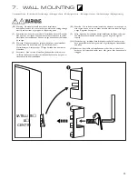
Page 18: ...F Installation Murale D Schablone f r Wandmontage I Montaggio a Parete ES Montage en Pared P Montagem na parede NL Wandmontage DK V g Montering 7 WALL MOUNTING 16...

Page 19: ...F Positionnement D Aufstellung I Posizionamento ES Posicionamiento P Posicionamento NL Plaats en aansluiting van het netsnoer DK Placering 8 POSITIONING A B C D D A E 17...

Page 20: ...F Connexions D Anschl sse I Collegamenti ES Conexiones P Liga es NL Aansluitingen DK Forbindelser 9 CONNECTIONS 18...

Page 21: ...F Connexions D Anschl sse I Collegamenti ES Conexiones P Liga es NL Aansluitingen DK Forbindelser 9 CONNECTIONS 19...

Page 22: ...commandes D Einstellen der Bedienungselemente I regolazione dei comandi ES Ajuste de los controles P Ajuste dos comandos NL bediening van de regelaars DK Justering af betjeningsknapperne 10 ADJUSTING...

Page 23: ...LF Crossover Frequencies 300 Hz 3 kHz Frequency range 3 dB 100 Hz 30 kHz Amplifier Requirement 10 100 Watts Sensitivity 2 83 V 1 m 87 dB Maximum Output 104 dB SPL 1 m Impedance 8 Net Weight 2 3 kg 5 0...

Page 24: ...oofer LF Drive Unit 1 x 250 mm 10 in Frequency range 15Hz 140Hz Amplifier 250 Watts built in Maximum Output SPL 108 dB Low Level Signal Inputs RCA phono sockets Low Level Signal Outputs RCA phono sock...

Reviews: