


4.3 Connection of the control
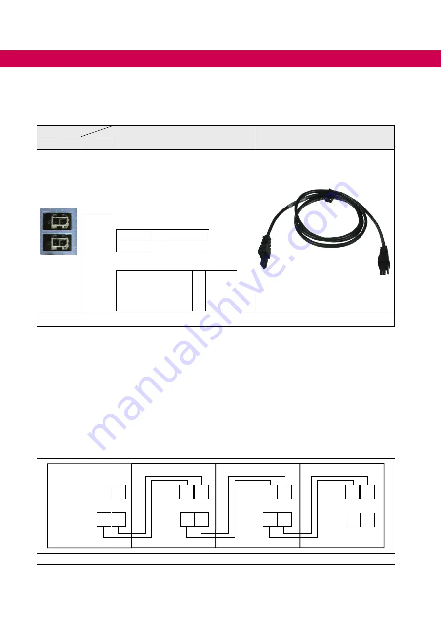
4.3.1 Error chain terminal X2C, X2D
Channel
Description
Connecting cable error linkage circuit
2
1
Name
X2C
The terminal strips X2C and X2D are in-
ternally parallel connected. Thus, each
terminal strip can be used as input or out-
put.
Based on the power supply unit the error
chain contains two channels and can sup-
ply maximally 64 axis modules.
Status channel 1:
OK
= U > 9 V
Error
= U < 5 V
Status channel 2:
Release axis
modules
= U < 5 V
no release axis
modules
= U > 9 V
X2D
Figure 16: Error chain terminal X2C, X2D
4.3.1.1 Error linkage circuit (channel 1)
The first error channel is an error linkage circuit. If there is an error in a module, the other
modules can be notified of the error directly via this channel. The response to the error
can be parameterized.
4.3.1.2 Error power supply unit (channel 2)
At this error channel the axis modules get the information that the power supply unit is in
error status and the modulation of all axis modules must be switched off.
4.3.1.3 Wiring example error linkage circuit
X2C 1 2
X2D 1 2
X2C 1 2
X2D 1 2
X2C 1 2
X2D 1 2
X2C 1 2
X2D 1 2
Figure 17: Wiring example error linkage circuit
46
CONNECTION OF THE CONTROL
All manuals and user guides at all-guides.com