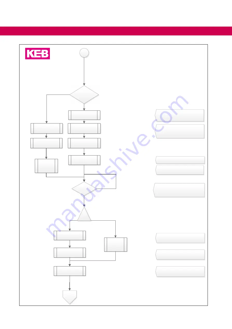
KEB COMBIVERT 14H6 Series Instructions For Use Manual Download Page 78

Precharging on

set control word 

co00 := 3 

ST with control 

word?

set I2

yes

no

dr55 = 14?

set control word 

co00 := 11 

set control word 

co00 := 3

set control word 

dr54 := 0 

Identification  off

no

yes

Identification successfully completed?

1

2

3

4

5

6

7

8

9

10

11

modulation on

or

toggle I2 

Modulation off

precharging off

set control word 

co00 := 0

Start identification, see programming 

manual determination of the network 

impedance

set dr54 := 1

set dr54 := 1

set dr99 := 0

set dr99 := 0

sub procedure

mains ident

12

13

I2 start precharging und modulation on

78

 START-UP

Summary of Contents for COMBIVERT 14H6 Series

Page 1: ...COMBIVERT H6 INSTRUCTIONSFORUSE INSTALLATION ACTIVE INFEED CONTROLLER AIC AND CHARGING MODULE Translation of original manual Document 20105449 EN 05 ...

Page 2: ......

Page 3: ... case of non observance of this safety instruction WARNING Dangerous situation which may cause death or serious injury in case of non observance of this safety instruction CAUTION Dangerous situation which may cause minor injury in case of non ob servance of this safety instruction NOTICE Situation which can cause damage to property in case of non obser vance RESTRICTION Is used when certain condi...

Page 4: ...s well as any user specific advice in spoken and written and through tests are made to best of our knowledge and information about the intended use However they are regarded as being only informal and changes are expressly reserved in particular due to technical changes This also applies to any violation of industrial property rights of a third party Selection of our units in view of their suitabi...

Page 5: ...asic Safety Instructions 14 1 1 Target group 14 1 2 Transport storage and proper use 14 1 3 Installation 15 1 4 Electrical connection 16 1 4 1 EMC compatible installation 17 1 4 2 Voltage test 17 1 4 3 Insulation measurement 17 1 5 Start up and operation 18 1 6 Maintenance 19 1 7 Repair 20 1 8 Disposal 20 2 Product Description 21 2 1 Specified application 22 2 2 Unintended use 22 2 3 Product featu...

Page 6: ...ne wave EMC filter with DC regeneration 41 4 Installation and Connection 42 4 1 Construction of the device 42 4 1 1 Status LED displays AIC module 48 4 1 1 1 Status LED 1 AIC module 48 4 1 1 2 Status LED 2 safety module 48 4 2 Structure of the charging module 49 4 2 1 Status LED displays charging module 52 4 2 2 Status LED charging module 52 4 3 Connection of the power unit 54 4 3 1 Connection of ...

Page 7: ... module 64 4 5 1 Module type 0 terminal block X2B 64 4 5 2 Control release 64 5 Certification 65 5 1 CE Marking 65 5 2 UL Marking 65 5 3 Further informations and documentation 66 6 Cooling System 67 6 1 Installation of water cooled units 67 6 1 1 Heat sink and operating pressure 67 6 1 2 Materials in the cooling circuit 67 6 1 3 Requirements on the coolant 68 6 1 4 Connection to the cooling system...

Page 8: ...Terminal block X1B 52 Figure 24 Connection for protective earth and function earth 52 Figure 25 Status LED displays charging module 52 Figure 26 View upper side of the device 53 Figure 27 Connection of the DC bus 54 Figure 28 Connection of the 24V bus 54 Figure 29 Connection of filter AIC and charging module 55 Figure 30 Connection of filter AIC and charging module 56 Figure 31 Wiring example temp...

Page 9: ... H6 modules 30 Table 10 Mounting instructions for control cabinet installation 32 Table 11 Sine wave EMC filter with DC regeneration 41 Table 12 Status LED 1 AIC module 48 Table 13 Status LED 2 safety module 48 Table 14 Status LED charging module 52 Table 15 EtherCat System bus socket X4B 59 Table 16 Diagnosis Visualisation X4A 59 Table 17 Technical data of the outputs 60 Table 18 Wire end ferrule...

Page 10: ...y technology EN 61508 1 7 for the size of error probability 0V Earth potential free common point 1ph 1 phase mains 3ph 3 phase mains AC AC current or voltage AFE From 07 2019 AIC replaces the pre vious name AFE AFE filter From 07 2019 AIC filter replaces the previous name AFE filter AIC Active Infeed Converter AIC filter Filter for Active Infeed Converter Application The application is the intende...

Page 11: ...r with 8 lines SCL Synchronous sensorless closed loop SELV Safety Extra Low Voltage 60V SIL The security integrity level is a measure for quantifying the risk reduction Term used in the safety technology EN 61508 1 7 SS1 Safety function Safe stop 1 in ac cordance with IEC 61800 5 2 SSI Synchronous serial interface for encoder STO Safety function Safe Torque Off in accordance with IEC 61800 5 2 TTL...

Page 12: ...rements and tests IEC 60664 1 EN60721 3 1 Classification of environmental conditions Part 3 1 Classification of groups of environmental parameters and their severities Section 1 Storage IEC 60721 3 1 German version EN 60721 3 1 EN60721 3 2 Classification of environmental conditions Part 3 Classification of groups of environmental parameters and their severities Section 2 Transportation and handlin...

Page 13: ...ors IEC 64 1610 CD DIN VDE 0100 729 Low voltage electrical installations Part 7 729 Requirements for special installations or locations Operating or maintenance gangways IEC 60364 7 729 2007 modified German implementation HD 60364 7 729 2009 DNVGL CG 0339 Environmental test specification for electrical electronic and programmable equipment and systems EN1037 Safety of machinery Prevention of unexp...

Page 14: ...omation KG 1 1 Target group This instruction manual is determined exclusively for electrical personnel Electrical per sonnel for the purpose of this instruction manual must have the following qualifications Knowledge and understanding of the safety instructions Skills for installation and assembly Start up and operation of the product Understanding of the function in the used machine Detection of ...

Page 15: ...components are bent and or isolation distances are changed The device must not be put into operation in case of mechanical defects Non compliance with the applicable standards Do not allow moisture or mist to penetrate the unit Avoid dust permeating the device Allow for sufficient heat dissipation if installed in a dust proof housing Note installation position and minimum distances to surrounding ...

Page 16: ...current in the pro tective earth conductor When a residual current protective device RCD or a residual current monitoring device RCM is used for the protection against direct or indirect contact only a RCD or RCM type B is permitted on the power supply side of this product Drive converters with a leakage current 3 5mA AC current 10mA DC current are intended for a stationary connection Protective e...

Page 17: ... using components without isolated inputs outputs it is necessary that equi potential bonding exists between the components to be connected e g by the equi potential line Disregard can cause destruction of the components by equalizing currents 1 4 1 EMC compatible installation Observance of the limit values required by EMC law is the responsibility of the customer Notes on EMC compatible installat...

Page 18: ...ware supported functions is not suf ficient It is imperative to install external protective measures e g limit switch that are independent of the drive converter Secure motors against automatic restart CAUTION High temperatures at heat sink and coolant Burning of the skin Cover hot surfaces safe to touch If necessary attach warning signs on the system Before touching check the surface and coolant ...

Page 19: ...f the motor is still running during a restart of the drive converter mains on e g due to large rotating masses Switching an the input For applications that require cyclic switching off and on of the drive converter maintain an off time of at least 5 min after the last switch on If you require shorter cycle times please contact KEB Automation KG 1 6 Maintenance The following maintenance work has to...

Page 20: ...called B2B devices Manufacturers of B2B devices are obliged to take back and recycle devices manufac tured after 14 08 2018 These devices may not be disposed at the collection centres of public sector disposal organisations If no deviating agreement has been made between the customer and KEB or no deviating mandatory legal regulation exists KEB products marked in this way can be returned Company a...

Page 21: ... regeneration The AIC can regenerate excess energy in sinusoidal form from the DC bus connection into the mains Precharging is required when using an AIC 24V power supply module Provides the 24V DC power supply for the individual modules The input is supplied from the mains DC bus The 24V power supply module can be omitted if an existing 24V supply is to be used Control module with 24V power suppl...

Page 22: ...rk under exceptional condi tions or if essential functions life supporting measures or an extraordinary safety step must be fulfilled the necessary reliability and security must be ensured by the machine builder Residual risks Despite intended use drive converters can reach unexpected operating conditions in case of error with wrong parameterization by faulty connection or unprofessional inter ven...

Page 23: ...tion of displays or service tools Inputs and outputs 4 digital inputs 4 digital outputs Separate supply Internal supply of the control unit and driver power unit are safe separated Internal fuses The driver power unit is connected via internal fuses to the DC link bus Cooling System universally by flat rear and air heat sink 1 EtherCAT is a registered trademark and patented technology li censed by...

Page 24: ...l data 2 Special overload behaviour A Z Customer special version firmware and download Housing Flat rear heat sink B 50mm E 200mm C 100mm G 300mm Air heat sink P 50mm U 200mm S 100mm W 300mm Control type A KEB standard with control release Power supply and regenerative unit D Active Infeed Converter AIC for sine wave rege neration F Charging module Series COMBIVERT H6 multi axis drive system Inver...

Page 25: ...Class Notes Surrounding temperature EN 60721 3 3 3K3 5 40 C extended to 10 45 C Coolant inlet tem perature Air 5 40 C 10 45 C Water 5 40 C Relative humidity EN 60721 3 3 3K3 5 85 without condensation Version and degree of protec tion EN 60529 IP20 Protection against foreign material ø12 5mm No protection against water Non conductive pollution occasional conden sation when PDS is out of service Sit...

Page 26: ...on limits EN 60721 3 3 3M4 Vibration amplitude 3 5mm 2 9Hz Acceleration amplitude 10m s 9 200Hz EN 61800 5 1 Vibration amplitude 0 075mm 10 57Hz Acceleration amplitude 10m s 57 150Hz Shock limit values EN 60721 3 3 3M4 100m s 11ms Pressure in the water cooler Max operating pressure 10bar Table 3 Mechanical ambient conditions 3 1 3 Chemical mechanical active substances Storage Standard Class Notes ...

Page 27: ...ble length Radiated interferences EN 61800 3 C2 Interference immunity Standard Level Notes Static discharges EN 61000 4 2 8kV 4kV AD air discharge CD contact discharge Burst Ports for process measurement control lines and signal interfaces EN 61000 4 4 2kV Burst Power ports EN 61000 4 4 4kV Surge Power ports EN 61000 4 5 1kV 2kV Phase phase Phase ground Cable fed disturbances in duced by high freq...

Page 28: ...the connection point Skn Sn 15 Skn Sn 350 Power dissipation heat sink 4 PDext W 181 698 1090 1850 2315 1979 Power dissipation interior 4 PDint W 53 95 131 175 218 189 Max heat sink temperature THS C 80 Insulation resistance Udc 500V Rsio MΩ 5 Supply control unit Rated input voltage UCU_dc V 24 10 Rated input current 5 ICU_dc A 600mA Additional input current for air cooler ICU_dc A 0 5 2 4 2 4 3 6 ...

Page 29: ... precharging current IO_dc A 5 Braking transistor GTR7 Max brake power switching cycle 40 P_max kW 46 2 Max braking current IB_max_dc A 146 176 Min braking resistor RB_min Ω 6 10 5 10 Connection cross section mm 16 Response voltage U_dc V 780 Switching frequency fSN kHz 4 Switching cycle based on 120s cycle time ED 40 30 Other data Power dissipation interior PDint W 5 Max heat sink temperature THS...

Page 30: ...10 12 double axis module 195 195 390 13 280 14 390 15 560 16 705 18 1020 19 1360 20 1650 21 1950 22 2350 23 3100 24 3900 25 4700 Active Infeed Controller AIC Device size Capacity in µF 14 390 19 1650 21 1950 23 3300 24 3900 26 5200 Table 9 DC link capacities of the H6 modules 30 DC link capacities of the H6 modules ...

Page 31: ...re and the displacement between the units must be kept to a minimum CAUTION Hot Surface Heat sinks can reach temperatures which can cause burns when touch ing If in case of structural measures a direct contact cannot be avoided a warning notice hot surface must be mounted at the machine If construction conditioned the control cabinet cannot be without indoor ventilation ap propriate filters must a...

Page 32: ...at sink ATTENTION Overheating of the device Never operate flat rear devices without main cooler Select suitable cooling surfaces e g water heat sink ribbed heat sink machine base Screw the flat rear of the devices to the cooling surface Ensure good thermal conductivity e g thermal paste The machine builder is responsible for the cooling of the units Heat conducting paste Information about the corr...

Page 33: ...ailable if no usable cooling surface exists at customer side Heat sink Cabinet outcut Size L1 in mm L2 in mm L3 in mm 04H6TFW 0400 452 435 406 06H6TFW 0600 652 635 606 08H6TFW 0800 852 835 806 10H6TFW 1000 1052 1035 1006 12H6TFW 1200 1252 1235 1206 Figure 2 Main heat sink for COMBIVERT H6 ...

Page 34: ...ensions and weights of modules with flat rear heat sink 198 50 407 60 5 395 7 200 300 150 50 50 Housing Module width in mm Weight in kg B charging module 50 3 8 C 100 5 8 E 200 12 5 G 300 18 Figure 3 Dimensions and weights of the modules ...

Page 35: ...chanical installation 3 4 5 Dimensions and weights of modules with air heat sink 49 7 Ø 6 5 7 395 407 11 109 289 Housing Module width in mm Weight in kg P charging module 50 5 5 Figure 4 Dimensions housing P ...

Page 36: ...36 Mechanical installation 395 7 407 99 7 50 Ø 6 5 109 289 Housing Module width in mm Weight in kg S 100 9 Figure 5 Dimensions housing S ...

Page 37: ...37 Mechanical installation 150 199 Ø 7 395 407 7 109 289 Housing Module width in mm Weight in kg U 200 17 Figure 6 Dimensions housing U ...

Page 38: ...38 Mechanical installation 150 250 299 Ø 7 7 394 5 407 109 289 Housing Module width in mm Weight in kg W 300 28 Figure 7 Dimensions housing W ...

Page 39: ... 1000 36 25 275 21 5 1 19H6J4F 1000 60 42 395 16 50mm AWG 6 0 4Nm 34 2 21H6J4F 1000 54 37 4 360 32 2 21H6J4F 1001 90 62 535 42 5 2 IN Rated current S Apparent power PD Power dissipation Figure 8 AIC filter 3x400VAC for switching frequency 8 16kHz Filter connection Ring crimp connectors M8 and two terminal blocks 4 mm for fan and temper ature sensor KTY switch T1 2 are used for size 26Z1 If a stand...

Page 40: ... 75 590 16 50mm AWG 6 0 4Nm M8 40 2 24H6J4G 1000 180 8 125 1100 M10 Stud 25Nm 220lbinch M10 68 3 26H6J4G 1000 1 150 8 104 695 26H6J4G A000 150 8 104 695 M10 Stud 25Nm 220lbinch M10 60 3 26Z1K04 1000 2 250 4 173 1300 M8 12Nm M8 91 6 1 IN Rated current fSN Switching frequency S Apparent power PD Power dissipation Figure 9 AIC filter 3x400VAC for switching frequency 4 16kHz 1 26H6J4G 1000 with sinus ...

Page 41: ... 24 0SZ1I05 1001 24Z1B04 1000 24E6T60 3000 180 270 4 23 0XZ1I05 1001 27Z1B04 1000 22E6T60 3000 145 290 26 0XZ1I05 1001 27Z1B04 1000 24E6T60 3000 200 378 26 0XZ1I05 1001 27Z1B04 1000 26U5A0U 3000 250 378 Table 11 Sine wave EMC filter with DC regeneration NOTICE After an overload Iin_max of 60s a partial load operation of 81 of the rated current IN is mandatory for 540s Further information can be fo...

Page 42: ... to approx 45 degrees until the plates solve above from the mounting Remove the cover forward Remove the cover from the DC bus Compress lug of the cover remove forward Figure 10 Front view of the device DANGER Hazardous voltage under the cover of the DC bus Secure isolation from supply of the DC bus at the power supply and regenerative unit 42 Installation and Connection ...

Page 43: ...24V bus X1C 1 X1C 3 24V bus 0V X1C 2 X1C 4 0V DC bus X1D 1 X1D 3 DC bus displayed with protection against contact for exterior devices DC bus X1D 2 X1D 4 Snap in for front cover Output to the filter X1A Figure 11 Connections of the front side 43 Installation and Connection ...

Page 44: ... 24 10 0 7Nm 6 2lbinch V W X1B BR Connection for 24V DC brake 0 25 1 5 mm AWG 28 16 0 25Nm 2 2 lbinch BR T1 Connection for PTC KTY filter temperature monitoring T2 PE Connection for shielding earthing M6 stud for ring crimp connector 1 3Nm 11 5lbinch Figure 12 View of the bottom of the device size C S The terminal blocks meet the requirements of EN 60947 7 1 44 Installation and Connection ...

Page 45: ...ng torque X1A U Connection to the filter Connect inphase 35 95mm AWG 4 0 15Nm 132lb inch V W PE Connection for shielding earthing M8 stud for ring crimp connector 12Nm 110lbinch Figure 13 View of the bottom of the device size E U The terminal blocks meet the requirements of EN 60947 7 1 45 Installation and Connection ...

Page 46: ...nnection to the filter Connect inphase M10 stud for ring crimp connector max width 30mm 12Nm 110lbinch V W PE Connection for shielding earthing M8 stud for ring crimp connector 12Nm 110lbinch Figure 14 View of the bottom of the device size G W The terminal blocks meet the requirements of EN 60947 7 1 46 Installation and Connection ...

Page 47: ... link and error output of the axis modules X2D Error chain 2 1 X4A reserved 1 6 reserved TxD RS232 2 7 DGND reference potential RxD RS232 3 8 TxD A RS485 RxD A RS485 4 9 TxD B RS485 RxD B RS485 5 X4C EtherCAT out LED 1 TX Speed 2 TX 3 RX 4 X4B EtherCAT in 5 6 RX Link Activity 7 LED 8 X2B Safety module type 0 default is displayed here 4 Brake no function 3 0V Reference potential 2 24V Output DC 24V...

Page 48: ...voltage supply of the device yellow Device initialised green Device ready for operation red Device in error routine Table 12 Status LED 1 AIC module 4 1 1 2 Status LED 2 safety module The LED indicate the state of the safety module LED Status off No voltage supply of the safety module green Safety module ready for operation red Safety module in error routine Table 13 Status LED 2 safety module 48 ...

Page 49: ...ve above from the mount ing Remove the cover forward Remove the cover from the DC bus Compress lug of the cover remove forward Figure 17 Front view of the device DANGER Hazardous voltage under the cover of the DC bus Secure isolation from supply of the DC bus at the power supply and regenerative unit The terminal blocks meet the requirements of EN 60947 7 1 49 Installation and Connection ...

Page 50: ...g length 10mm C1 FT2 Temperature monitoring of the AIC filter FT1 RT2 Temperature monitoring of the braking resistor RT1 Figure 19 Terminal block X1E X1F Name Function Connection data C out Control for supply regenerative contactor switches after comple tion of the precharging permissible connection cross sec tion 0 2 2 5mm AWG 24 12 Stripping length 10mm max load 6A 1500VA max inductive load 24VD...

Page 51: ...resistor Figure 21 View rear side of the device X1A Name Function Conductor cross section Tightening torque L1 L2 L3 Mains connection for pre charging 0 2 6mm AWG 24 10 0 7Nm 6 2lbinch PE Connection for protective earth DC link connection for sine wave EMC filter Figure 22 Terminal block X1A 51 Installation and Connection ...

Page 52: ...rth M8 4 5Nm 40lbinch Figure 24 Connection for protective earth and function earth 4 2 1 Status LED displays charging module Status LED 1 without function Status LED 2 Charging module Figure 25 Status LED displays charging module 4 2 2 Status LED charging module LED Status off No voltage supply of the device yellow Device initialised green Device ready for operation red Device in error routine Tab...

Page 53: ...tput Dig output 4 8 7 0V Dig output 3 6 5 0V Dig output 2 4 3 0V Dig output 1 2 1 0V X2C Error chain 2 1 Charging status of the DC link and error output of the axis modules X2D Error chain 2 1 X4A reserved 1 6 reserved TxD RS232 2 7 DGND reference potential RxD RS232 3 8 TxD A RS485 RxD A RS485 4 9 TxD B RS485 RxD B RS485 5 X4C no function X4B no function Figure 26 View upper side of the device 53...

Page 54: ...e devices upper rail DC lower rail DC Place plastic cap as protection against accidental contact at the end of the system Torx oval head screw M4x10 required tool Torx screw driver TX20 Tightening torque 3 0Nm bridge 1 1 1 2Nm plastic cap Figure 27 Connection of the DC bus Attach the cover for the DC bus again after the installation 4 3 2 Connection of the 24V bus X1C The 24V bus supplies the cont...

Page 55: ...emperature switch 5 AIC filter with fan and temperature monitoring switch off 6 Mains contactor K1 with protective circuit 7 Charging module 8 AIC module 9 Axis module 10 Superior control optional 11 Motor 12 Decoupling relay with protective circuit the decoupling relay is not required if ensured that the load capac itiy of the relais contact is not exceeding Figure 29 Connection of filter AIC and...

Page 56: ...perature switch 5 AIC filter with fan and temperature monitoring switch off 6 Mains contactor K1 with protective circuit 7 Charging module 8 AIC module 9 Axis module 10 24V power supply module with superior control 11 Motor 12 Decoupling relay with protective circuit the decoupling relay is not required if ensured that the load capac itiy of the relais contact is not exceeding Figure 30 Connection...

Page 57: ...he input of the charg ing unit Thermal contact NC contact minimum switching current 2mA R T1 R T2 Figure 31 Wiring example temperature monitoring NOTICE If no braking resistor is required a bridge must be installed between R T1 and R T2 to evaluate the input otherwise there is no precharging and modulation 57 Connection of the power unit ...

Page 58: ...is modules U 9V X2D Figure 32 Error chain terminal X2C X2D 4 4 1 1 Error chain channel 1 The first error channel is an error chain If there is an error in a module the other mod ules can be notified of the error directly via this channel The response to the error can be parameterized 4 4 1 2 Error power supply unit channel 2 At this error channel the axis modules get the information that the power...

Page 59: ...yellow Speed 1 8 X4B EtherCAT IN 6 RX 7 off 10MBit 8 on 100Mbit Table 15 EtherCat System bus socket X4B Does not apply to the charging module 4 4 3 Diagnosis Visualisation X4A The integrated RS232 485 interface serves for the connection of service tools e g COMBIVIS and displays Telegram DIN66019II is used as communication protocol Interface Standard Connecting cable RS485 TIA EIA 485 and ISO 8482...

Page 60: ... wheeling diode max 300mJ Table 17 Technical data of the outputs 4 4 3 3 Assignment of the interfaces 5 4 3 2 1 9 8 7 6 5 4 3 2 1 9 8 7 6 reserved do not assign 1 6 reserved do not assign TxD RS232 2 7 DGND reference potential RxD RS232 3 8 TxD A RS485 RxD A RS485 4 9 TxD B RS485 RxD B RS485 5 Figure 34 Assignment of the interfaces 4 4 4 Digital inputs and outputs X2A Additionally to the central i...

Page 61: ... 15 mm Table 18 Wire end ferrules and stripping length Front view 18 a b a Pusher b Wire hole Figure 35 Assembly of the control cable Press pusher by hand Insert connecting wires into the respective hole that no single wires can be seen from the outside or bend outward A first resistance must be overcome when inserting Release the pusher Check that the connecting wire is fixed and can not be pulle...

Page 62: ...geable 2 1 0V Figure 36 Assignment of the terminal block X2A AIC module 4 4 5 2 Assignment of the terminal block X2A charging module Digital inputs and outputs Function Default setting Term 1 2 3 4 5 6 7 8 9 10 11 12 13 14 15 16 Term Function Digital input DI4 Not preset 16 15 24 V 0 7 Adc Digital input DI3 Not preset 14 13 24 V 0 7 Adc Digital input DI2 Not preset 12 11 24 V 0 7 Adc Digital input...

Page 63: ...outputs DO1 4 0V IL_max Figure 39 Connection of the digital outputs DO1 DO4 4 4 5 5 Example for the control of digital inputs and digital outputs DO1 DI1 DO2 DI2 DO3 DI3 DO4 DI4 Operation with hardware release The 24V for the control of the inputs can be con trolled with the set output DO4 Figure 40 Example for the control of digital inputs and digital outputs 63 Connection of the control ...

Page 64: ...ble cross sections see section Assembly of the wires to PUSH IN termi nals Figure 41 Safety module type 0 terminal block X2B top view The digital inputs are specified in accordance with IEC61131 2 type 3 Status 0 Status 1 3 5V 11 30V 4 5 2 Control release The driver modules of the power modules are supplied with voltage by switching the control release X2B 2 24V X2B 1 ST X2B 2 24V X2B 3 0V X2B 1 S...

Page 65: ...zed standards of the series EN 61800 5 1 for drive converters were used The COMBIVERT is a product of limited availability in accordance with EN 61800 3 This product may cause radio interference in residential areas In this case the operator may need to take corresponding measures Depending on the design the machine directive EMC directive Low Voltage Directive and other directives and regulations...

Page 66: ...nd information for construction and development Input fuses in accordance with UL Programming manual for control and power unit Motor configurator to select the appropriate drive converter and to create downloads for parameterizing the drive converter Approvals and approbations Declaration of conformity CE TÜV certificate FS certification Others COMBIVIS the software for comfortable parameterizati...

Page 67: ...ng pressure was executed Pay attention to the guidelines 97 23 EC of pressure units 6 1 2 Materials in the cooling circuit For the screw connections and also for the metallic articles in the cooling circuit which are in contact with the coolant electrolyte a material is to be selected which forms a small voltage difference to the heat sink in order to avoid contact corrosion and or pitting corrosi...

Page 68: ...uminum is particularly corroded by lixiviums and salts The optimal pH value for aluminum should be in the range of 7 5 8 0 Abrasive substances Abrasive substances as used in abrasive quartz sand clogging the cooling circuit Copper cuttings Copper cuttings can attach the aluminum and this leads to a galvanic corrosion Copper should not be used together with aluminum due to electro chemical voltage ...

Page 69: ...ce with the manual The connection to the coolant must be carried out with flexible pressure resistant hoses and secured with clamps Pay attention to flux direction and check tightness The cooling flow must always be started before starting the KEB COMBIVERT The connection to the cooling system can occur as closed or open cooling circuit The connection to a closed cycle cooling circuit is recommend...

Page 70: ...3 0 1 4 6 8 9 15 18 7 3 1 4 7 9 11 13 15 20 12 4 1 5 9 12 14 16 18 20 25 8 0 5 10 13 16 19 21 23 25 30 6 3 10 14 18 21 24 26 28 30 35 2 8 14 18 22 25 28 31 33 35 40 1 11 18 22 27 31 33 36 38 40 45 4 15 22 27 32 36 38 41 43 45 50 8 19 28 32 36 40 43 45 48 50 Table 21 Supply of temper coolant Temperature control The cooling system can be connected by means of pneumatic or magnetic valves A re lay is...

Page 71: ...min 20 l min 10 l min 5 l min Figure 43 Coolant heating depending on power loss 6 1 7 Typically fall of pressure depending on the rate of flow bar 0 0 0 1 0 2 0 3 0 4 0 5 0 6 0 7 0 8 0 9 1 0 1 1 1 2 1 3 1 4 1 5 1 6 1 7 0 5 10 15 20 25 30 35 40 45 50 l min Figure 44 Typically fall of pressure depending on the rate of flow 71 Cooling System ...

Page 72: ...t start up Step by step start up H6 AIC 7 1 Default setting The COMBIVERT H6 AIC is an universally applicable power supply regenerative unit that requires an individual adjustment of the basic settings depending on the mains sup ply used filters and the connected devices The appropriate COMBIVIS files can be downloaded from www keb co uk under the search term Download H6 AFE Filter 72 Start Up ...

Page 73: ... ofcommunication between PC and AFE arealso possible de15 0 set co08 2 Deviceis reset to factory settings Requirement Hardwarecircuit electrically checked Application meets the mains connection requirements Check if H6 AFE device devicetype Node_1_H6_active_front_end set co09 1 wrong unit yes no co09 counts up co09 0 Restart drive communication lost Reset deletes all data Also operating hours etc ...

Page 74: ...hing frequency is included Internet available copy LCLFilter data dr15 dr17 dr49 dr53 dr65 dr66 Reset deletes all data Also operating hours etc See programming manual LCL filter 10 11 12 13 14 15 16 17 18 19 20 yes no yes no is the AFE rated current de28 rated filter current set dr12 max Filter current de28 100 yes no is max AFEFilter current de29 in dependence on the cooling of the AFE LCL filter...

Page 75: ...ontrol voltageis for example at 400V AC min 680V DC yes no dr12 rated current ofMCB de28 100 Commissioning under test environment de28 de29 dr12 is the mains supply rated device power yes no current set dr12 max Filter current de28 100 yes no is max AFEFilter current de29 in dependence on the cooling of the AFE LCL filter part load is possible Is the apparent current limited dr12 max current appli...

Page 76: ...no yes is lineinductance network resistance known set control word dr99 0 set co00 3 38 39 40 42 43 44 45 data saved precharging on check and set cu21 1 DC voltage see programming guide DC Bus PID Set point set cu99 4 according to the application optimize the voltagePID the input ofvoltage set point is adapted immediately the DC control voltageis for example at 400V AC min 680V DC Commissioning wi...

Page 77: ...44 45 46 data saved ST precharging on control word co00 3 commissioning at costumer site no yes on site commissioning 47 48 50 49 Final commissioning on site after delivery to the customer commissioning at customer site Modulation off Precharging off 51 53 52 55 54 decision action start end Explanation external HW final function test set point voltage reached and AFE modulates 56 77 Start Up ...

Page 78: ...ion off no yes Identification successfully completed 1 2 3 4 5 6 7 8 9 10 11 modulation on or toggleI2 Modulation off precharging off set control word co00 0 Start identification see programming manual determination of the network impedance set dr54 1 set dr54 1 set dr99 0 set dr99 0 sub procedure mains ident 12 13 I2 start precharging und modulation on 78 Start Up ...

Page 79: ... top to bottom The direction of the arrow gives the sequence of the individual steps The order is important Some settings are based on other settings which need to be set in advance 1 With software V1 4 the setpoint of the control voltage Target Uic is indicated in parameter IDText cu18 instead of parameter cu21 56 column number 56 Figure 45 Step by step start up H6 AIC 79 Start Up ...

Page 80: ...Pre series 01 2016 08 Heatsink concepts wrong terminal 02 2017 09 New CI general revision linkage with InCopy components 03 2018 05 Editorial changes 04 2019 06 Product description adapted updates have been made 05 2020 05 Change of the assignment table for the filters and the flow chart ...

Page 81: ...net www keb jp MORE KEB PARTNERS WORLDWIDE www keb de de contact contact worldwide P R China KEB Power Transmission Technology Shanghai Co Ltd No 435 QianPu Road Chedun Town Songjiang District 201611 Shanghai P R China Tel 86 21 37746688 Fax 86 21 37746600 E Mail info keb cn Internet www keb cn Poland KEB Automation KG Tel 48 60407727 E Mail roman trinczek keb de Internet www keb de Republic of Ko...

Page 82: ...Automation with Drive www keb de KEB Automation KG Suedstrasse 38 32683 Barntrup Tel 49 5263 401 0 E Mail info keb de ...

Reviews: