background image

33


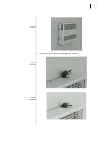
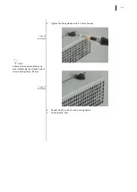
Figure 23 

Installation


Figure 24 

Installation


Figure 25 

Installation


2.


Insert the fixing clamps into the housings of the device. 


Summary of Contents for C6 HMI LC

Page 1: ...Document Part Version 20125246 GBR 00 C6 HMI C6 HMI LC Instruction Manual COMBICONTROL...

Page 2: ...2...

Page 3: ...I 4 3 19 2 8 1 Labels 19 2 9 Connection overview C6 HMI C6 HMI LC 5 7 and higher 20 2 9 1 Connection Label 20 2 9 2 Nameplate 21 2 10 Touchscreen 21 2 11 Putting in operation C6 HMI C6 HMI LC 22 2 11...

Page 4: ...to the target system 61 5 2 4 I O Fieldbus 61 5 2 5 Support for retentive data 62 5 2 6 Use in combination with COMBIVIS HMI Runtime 64 5 2 7 Use in combination with COMBIVIS connect 65 5 2 8 Limitat...

Page 5: ...5 SECTION 1 1 Introductory Information...

Page 6: ...istato il prodotto The symbol on the product or in its packaging indicates that this prod uct may not be treated as household waste Instead it shall be handed over the applicable collection point for...

Page 7: ...rir si este producto no se man pula de forma adecuada Para obtener informaci nes mas detalladas sobre el reciclaje de este producto p ngase en contacto con la adMinistraci n de su ciudad con su servic...

Page 8: ...embly installation storage commissioning operation and maintenance are required to ensure that the product operates safely d The indicated environmental conditions must be observed e The information i...

Page 9: ...installed complies with all the applicable EU and international regulation 1 12 2 Working on the control cabinet Open equipment The device is open equipment This means that the C6 HMI C6 HMI LC may on...

Page 10: ...10 SECTION 2 2 Description...

Page 11: ...cense is of one unique type and enables all the features at ones except for the CONTROL PRO Runtime which is not supported 2 2 Key features KEY FEATURES C6 HMI C6 HMI LC O S Microsoft Windows Embedded...

Page 12: ...figures show the various configurations 2 4 1 C6 HMI C6 HMI LC full aluminium front panel C6 HMI 4 3 Full aluminium front panel 5 7 7 0 W 8 4 10 1 W 10 4 12 1 12 1 W 15 0 15 6 W C6 HMI LC 5 7 Full alu...

Page 13: ...13 Figure 2 Full aluminium front panel detail 2 5 Front view 2 5 1 Full aluminium front panel Full aluminium front panel Touchscreen Display 2 1 1 2...

Page 14: ...h 5 7 8 4 10 4 12 1 15 0 dis play have a 4 3 aspect ratio whereas the systems with 4 3 7 0 W 10 1 W 12 1 W and 15 6 W display have a aspect ratio of 15 9 or 16 9 The 7 0 display provides 25 more surfa...

Page 15: ...nt de pending on display size Figure 6 C6 HMI C6 HMI LC 7 0 rear view Note the user manual refers to HMI 5 7 version Other versions will be discussed only when necessary 2 6 Rear view Ventilation hole...

Page 16: ...16 Figure 7 C6 HMI C6 HMI LC 8 4 rear view Aeration holes Mounting seal 1 2 1 2...

Page 17: ...17 Figure 8 C6 HMI 4 3 side view Figure 9 C6 HMI 4 3 side view 2 7 Side view Aeration holes Aeration holes Recess for fixing clamps 2 1 1 1 1 2 1 2 2 1...

Page 18: ...18 Figure 10 C6 HMI C6 HMI LC 5 7 side view Figure 11 C6 HMI C6 HMI LC 5 7 side view Aeration holes Recess for fixing clamps Aeration holes Recess for fixing clamps 1 2 2 1 1 1 2 1 2 1 2 2 2 1 2 2 1...

Page 19: ...l detail 2 8 Connection overview C6 HMI 4 3 DC supply unit COM TX LED Power on LED COM 1 RS232 422 485 MPI USB1 2 0 LAN1 100 Mbit s Buzzer Reset button COM RX LED 2 8 1 Labels On the rear panel are pr...

Page 20: ...erview C6 HMI C6 HMI LC 5 7 and higher Power DC input LAN1 100 Mbit s Fieldbus USB2 2 0 LAN2 10 100 Mbit s CV connect Reset button Power on LED SD card slot USB1 2 0 COM 1 RS232 422 485 MPI 2 9 1 Conn...

Page 21: ...erial number 2 10 Touchscreen Size Touchscreen Panel technology Standard 4 3 4 wire The touchscreen is installed from the back of the front panel There is a step between the front panel and the touchs...

Page 22: ...ect creation During the configuration phase you create the user interfaces for operation and monitoring of the technical process by using a PC on which is installed COMBIVIS studio HMI development env...

Page 23: ...s VBA Symbols Yes Yes Grid Yes Yes Synapsis Yes Yes Scheduler Yes Yes Editing Menu Yes Yes Style Source Management in Symbols Yes Yes IP Camera Viewer Yes Yes Alias management in Objects Yes Yes Alarm...

Page 24: ...e 21 Cross Reference Table 22 Debugger Dynamic Multilanguage Yes Yes Unicode support Yes Yes Drivers Max number of Driver 2 4 PLC Tag Importer Yes Yes Event Object Yes Yes Scaling Object Yes Yes Sched...

Page 25: ...25 SECTION 3 3 Installation and connection...

Page 26: ...indow from where you can select the desired orientation The selection is immediately applied and does not require to be saved in the registry 3 2 Checking the package contents Check the package conten...

Page 27: ...uitable for installation in Mounting cabinets Control cabinets Switchboards Consoles 3 4 1 Damage due to overheating The operative temperature must be between 0 and 50 C All HMI systems are designed f...

Page 28: ...15 mm for each side Y direction min 50 mm for each side Z direction min 10 mm 3 6 Preparing the mounting cut out In order to ensure a proper mounting of the system the material of the mounting cut out...

Page 29: ...6 2 Dimensions of the cut outs LCD TFT A B C D E F G H I K L M N weight kg 4 3 140 95 5 30 5 84 128 131 86 0 7 5 7 175 145 5 40 7 131 161 164 134 0 9 7 0 W 215 155 5 40 7 141 201 204 144 1 2 8 4 255...

Page 30: ...the system it is necessary to respect the positions of the clamps shown below The table below shows the number and the position of the clamps for each C6 HMI C6 HMI LC size System Clamp Quantity Clamp...

Page 31: ...31 C6 HMI C6 HMI LC 10 4 10 C6 HMI C6 HMI LC 12 1 10 C6 HMI C6 HMI LC 12 1 W 10 C6 HMI C6 HMI LC 15 0 10 C6 HMI C6 HMI LC 15 6 W 10 3 7 2 Tools to tighten the mounting clamps 1 5 mm hexagonal key...

Page 32: ...32 Figure 21 Installation Figure 22 Installation 3 7 3 Procedure 1 Insert C6 HMI C6 HMI LC into the mounting cut out from the front...

Page 33: ...33 Figure 23 Installation Figure 24 Installation Figure 25 Installation 2 Insert the fixing clamps into the housings of the device...

Page 34: ...ere to the permissible torque when tightening the threaded pin of the mounting clamp 0 2 Nm Figure 27 Installation 3 Tighten the fixing clamps with a 1 5 mm hex key 4 Repeat steps 2 and 3 for all moun...

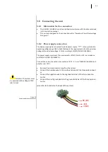
Page 35: ...e 18V to 36V that meets the requirements of a safe extra low voltage safe extra low voltage SELV according to IEC EN DIN EN UL60950 1 The power supply must meet the requirements of NEC Class2 or LPS i...

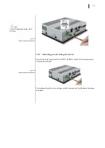
Page 36: ...ail Figure 30 Power supply connection detail 3 8 3 Switching on and testing the device Connect the power supply cable to C6 HMI C6 HMI LC Switch On the power supply The green led will light The displa...

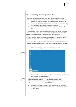
Page 37: ...ect the C6 HMI in LAN the LAN DHCP server automatically assigns an IP address to the C6 HMI C6 HMI LC If no DHCP server is available assign a static IP address to the C6 HMI C6 HMI LC which is compati...

Page 38: ...38 Figure 32 Connecting the configuration PC Figure 33 Connecting the configuration PC Click on Ok to save the settings Click on Start Settings Control Panel...

Page 39: ...necting the configuration PC Figure 35 Connecting the configuration PC Then double click on Registry Saver Click on the Save button and confirm clicking on Ok This operation will save your setting in...

Page 40: ...must Start COMBIVIS studio HMI Developing tool Load the project to transfer Click on the transfer icon see picture below The following window will appear Select TCP in the upper left list Write the I...

Page 41: ...lorer Note NAND NANDFlash Used internal memory to store the operating system It is a read only memory MMC MMCMemory Memory to store data and executables Read and Write memory SD SDMemory Removable Mem...

Page 42: ...42...

Page 43: ...43 SECTION 4 4 Commissioning the device...

Page 44: ...not possible to switch off the writing of MMCs You can always read and write the eMMC memory This memory is used to store data which are generated during the operation of the machine or plant and mon...

Page 45: ...em memory card while the project is running If you remove memory card while a project is running the project may stop Figure 42 Slot for memory card 4 3 Slot for memory card from 5 7 C6 HMI C6 HMI LC...

Page 46: ...46 Figure 43 Slot for memory card Figure 44 Slot for memory card Figure 45 Slot for memory card Push the card previously inserted Extract the memory card from the slot...

Page 47: ...47...

Page 48: ...48 SECTION 5 5 Commissioning a project...

Page 49: ...there is no project inside At first you need to transfer a project into C6 HMI C6 HMI LC After you download a project you can retransfer another project or another version of the same project without...

Page 50: ...guring the serial port Figure 47 Configuring the serial port Figure 48 Configuring the serial port Click on Start Settings Control Panel Double click on Serial Port Configuration Choose the type of se...

Page 51: ...nnecting the serial port A unique DB15 male connector hosts all serial protocols please check par 7 3 1 for pin out details so it is necessary to adapt this connection to plant needs KEB can supply co...

Page 52: ...6 Stopping the running project Please follow these steps to stop a running project 5 Select TCP in the upper left list 6 Insert the IP address of the C6 HMI C6 HMI LC 7 Click the button Stop Device P...

Page 53: ...To start a project in C6 HMI C6 HMI LC by using the configuration PC you must 8 Select TCP in the upper left list 9 Insert the IP address of the C6 HMI C6 HMI LC 10 Click the button Start Device Proj...

Page 54: ...explorer window of COMBIVIS studio HMI 2 Enable the property Debugger in the Properties window of COMBIVIS studio HMI Transfer the project to the C6 HMI C6 HMI LC and start running NOTE Ensure that t...

Page 55: ...e 54 Debugging the project Picture 55 Debugging the project The following window will appear Enter the IP address of the C6 HMI C6 HMI LC and click OK A new window opens that asks for the user and the...

Page 56: ...pts running in the project 5 1 9 Transfer the project from C6 HMI C6 HMI LC to the configuration PC This option allows you to transfer the project from C6 HMI C6 HMI LC to the con figuration PC in ord...

Page 57: ...check test and change the resources of the project 5 1 10 Backup and restore The C6 HMI C6 HMI LC has tools to backup and restore the contents of its internal memory in order to manage the project an...

Page 58: ...em Each task is executed at the specified time interval and according to the assigned priority Only when all the COMBIVIS studio 6 activities are over the CPU time goes to the other processes as they...

Page 59: ...ent must be properly configured in order to support the code compiler for C6 HMI LC systems You need COMBIVIS studio 6 version 6 2 1 0_3 5 3 50 or above installed on the PC COMBIVIS studio 6 installat...

Page 60: ...60 Create now a new project and insert the C6 HMI LC as new Device as shown in the following figure...

Page 61: ...ogin to start the communication 5 2 4 I O Fieldbus The implementation CONTROL Runtime for KEB C6 HMI LC systems supports the following I O fieldbuses EtherCAT with NO DC support distributed clock on L...

Page 62: ...ea is used Please check the COMBIVIS studio 6 manual for any additional detail about reten tive data The use of the retentive areas does not require any specific configuration except for declaring the...

Page 63: ...ore the energy inside the Micro UPS is fin ished and actually C6 HMI LC has not been switched off the following operations are carried on The display is switched on The USB ports are powered CONTROL R...

Page 64: ...oller inserting in the Real Time DB resource the driver called CODESYS as shown in the following figure The protocol uses a socket to communicate with the CONTROL Runtime through the Gateway component...

Page 65: ...project can be configured to communicate with more than one controller in these cases the system can act as a gateway and trans fer data through the different channels For further information about t...

Page 66: ...rameter in case the PLC program gets more than 25 of the CPU time the CONTROL Runtime will be stopped The user shall then properly change the PLC task timing in order to respect the limitation The max...

Page 67: ...67 SECTION 6 6 Maintenance...

Page 68: ...ation of the Touchscreen C6 HMI C6 HMI LC is designed to don t require touchscreen calibration but in some cases like update of the operating system you must recalibrate the touch screen To calibrate...

Page 69: ...n except for the re placing of the battery backup when necessary It is recommended to clean the touchscreen with a damp cleaning cloth and a display cleaning solution Note clean the front panel of the...

Page 70: ...off the HMI device or lock the touch screen b Spray the cleaning solution onto a cleaning cloth c Do not spray directly onto the display d Clean the display from the screen edge inwards 6 2 2 Backup...

Page 71: ...ment Figure 64 Backup battery replacement Figure 65 Backup battery replacement The following figures relate to the display models from 8 4 inches Remove the two screws as indicated in figure Remove th...

Page 72: ...72 Figure 66 Backup battery replacement Figure 67 Backup battery replacement Locate the battery position Remove the battery and replace it with one of the same model CR2032 3V...

Page 73: ...kly and effi ciently You can phone our staff in the service department and they will give you complete prompt advice on how to resolve your problems telephone 49 0 5263 401 0 Fax 49 0 5263 401 116 e m...

Page 74: ...74 SECTION 7 7 Technical specifications...

Page 75: ...y Log events Dynamic language change IL Logic SoftLogic VBA Multithreading ActiveX OCX CFR21 Part 11 Debugger Online Remote IP camera Dynamic trends Historical trends data analysis Recipes OPC DA Clie...

Page 76: ...resistive 15 0 5 wire analog resistive 15 6 5 wire analog resistive Motherboard Model All in one KEB R131 RTC Hardware with battery backup Buzzer Yes CPU Processor ARM Cortex A8 Freescale i MX535 1 G...

Page 77: ...ife at an av erage temperature of 45 C First load 6 min Rrearm time 90 sec Power consumption max with USB ports loaded 12 0W 5 7 13 0W 7 0 13 5W 8 4 15 5W 10 4 19 5W 12 1 SVGA 21 5W 15 0 23 0W 15 6 Th...

Page 78: ...ze 12 1 Resolution 800 x 600 SVGA Colors 16M Backlight Sidelight LED 12 1 W LCD size 12 1 Resolution 1280x800 WXGA Colors 16M Backlight Sidelight LED 15 0 LCD size 15 0 Resolution 1024 x 768 SXGA Colo...

Page 79: ...Note 1 Horizontal angle left right 70 70 Vertical angle up down 45 55 Contrast ratio 250 1 Response time increasing 50 ms Type Backlight LED LED life Note 2 40 000h default Note 3 and max Tamb 7 1 3 7...

Page 80: ...chnology TFT active matrix Display area 211 2 W x 158 4 H mm Resolution 800 x 600 pixel Display color 16M colors Pixel Pitch 0 264 W x 0 264 H mm Brightness 400 cd m2 Note 1 Horizontal angle left righ...

Page 81: ...ponse time increasing 2 ms Type Backlight LED LED life Note 2 100 000h default Note 3 and max Tamb 7 1 10 15 6 W Display characteristics 15 6 W display characteristics Dimensions 15 6 16 9 Technology...

Page 82: ...uipment Immunity characteristics EN 61000 6 2 Electromagnetic compatibility EMC Part 6 2 Generic standards Immunity for industrial environments EMC Directive 2014 30 EU ex 2004 108 EC Safety Conforms...

Page 83: ...n Data Receive Data RS 485 RS 422 Input output 11 Transmission Data Receive Data RS 485 RS 422 I O 12 Ring Indication RS 232 IN 13 Receive Data RS 422 IN 14 Receive Data RS 422 IN 15 N C N C Any polar...

Page 84: ...who deal with this handle questions on the entire range of products skilfully quickly and effi ciently You can phone our staff in the service department and they will give you complete prompt advice o...

Page 85: ...27 Installation 34 Figure 28 Power supply connection detail 35 Figure 29 Power supply connection detail 36 Figure 30 Power supply connection detail 36 Figure 31 Connecting the configuration PC 37 Figu...

Page 86: ...Backup battery replacement 70 Figure 62 Backup battery replacement 70 Figure 63 Backup battery replacement 71 Figure 64 Backup battery replacement 71 Figure 65 Backup battery replacement 71 Figure 66...

Page 87: ...ting the configuration PC 37 Table 24 Procedure 41 Table 25 System software characteristics 75 Table 26 MAIN FEATURES of CONTROL PLC WinCE ARM software 76 Table 27 System hardware characteristics 76 T...

Page 88: ...Croix St Nicolas 14 rue Gustave Eiffel F 94510 LA QUEUE EN BRIE fon 33 1 49620101 fax 33 1 45767495 net www keb fr mail info keb fr KEB UK Ltd 6 Chieftain Buisiness Park Morris Close Park Farm Welling...

Reviews: