


1-800-KEATING
|
ELECTRIC GRIDDLE - SERIES 2000
3
FIRST STEPS
POSITIONING
The griddle must be placed under an exhaust hood
with a fi re retardant system. Your ventilation hood,
when installed, must conform to the current ANSI/
NFPA 96 standard. ALL connections and placement
must comply with local and national codes. It is the
responsibility of the owner and local installer to comply
with these regulations when installing the griddle.
NOTE: NOT FOR OUTDOOR INSTALLATION.
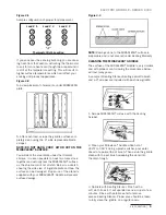
LEVELING
Your Miraclean® Griddle will operate at its highest
effi ciency when properly leveled. Place a level on the
griddle plate from side to side. For griddles on legs,
the bottom foot of the leg is adjustable. Turn clockwise
to decrease height or counterclockwise to increase
height until level. For griddles on stands with casters,
the casters are adjustable by loosening the jam nut
and turning the caster in or out. When the desired
level is reached, tighten the jam nut. Adjustments of
more than 3/4" are not recommended on any caster.
The same procedure should be followed to level the
griddle from front to back.
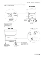
RESTRAINING DEVICES
For griddle installations on stands
with casters, casters and jam nuts
must be completely tightened.
Adequate means must also be
provided to limit the movement of
the appliance.
The restraint must be attached to
the rear of the griddle as close as
possible to the center line width
and the bottom of the cabinet back
to allow the restraining bolt to be
anchored to the cabinet back between the cabinet
bottom and inner liner to ensure positive support to
restrain griddle movement.
IF DISCONNECTION OF THE RESTRAINT IS NECESSARY,
IT MUST BE RECONNECTED WHEN THE MIRACLEAN®
GRIDDLE IS RETURNED TO ITS ORIGINALLY INSTALLED
POSITION.
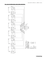
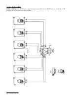
ELECTRICAL CONNECTION
The Keating Electric Miraclean® Griddle is equipped
with a three wire terminal block for customer connec-
tions. Compare the griddle terminal connections to
the appropriate wiring diagram for the griddle (see
pages 12 - 14 Wiring Diagram) to see if the griddle
is connected three phase or single phase. All wires,
cords, plugs, receptacles and circuit breakers must be
sized adequately for the full load rating of the griddle
as specifi ed by local codes or, in the absence of local
codes, by the current National Electrical Code ANSI/
NFPA 70 or the Canadian Electrical Code CAN 22.2 as
applicable.
The Electric Miraclean® Griddle is also equipped with
a grounding lug next to the terminal block. For proper
grounding procedures, see local codes or, in the
absence of local codes, the current National Electrical
Code ANSI/NFPA 70 or the Canadian Electrical Code
CAN 22.2 as applicable.
NOTE:
The connections to the griddle can be changed
in the fi eld from three phase to single phase or from
single phase to three phase. This can be done by
simply changing the wiring at the terminal block. To
change the connections for your griddle, see the wiring
diagram for your griddle on pages 12 - 13.
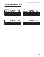
NOTE:
For griddles rated at 208-240 volts, the amper-
age ratings marked on the nameplates of the griddles
are listed at 240 volts as required by UL. If your
griddle uses a 208 or 220 volt system, refer to the
Electric Griddle Specifi cations on pages 15 to 17 to
determine the full load rating of the griddle.
NOTE:
A hole has been punched in the rear of the
griddle cabinet for a cord or conduit exit. If a cord is
used, the National Electrical Code, UL standards and
most local codes require a bushing or strain relief (not
provided by Keating) to protect the cord.
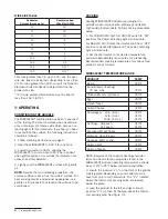
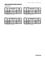
WIRE SIZE
Use the
WIRE SIZE TABLE
to help determine the
proper wire size for electrical service hook-up. Use the
largest amp value of the three conductors for 3-phase
installations when using the table. The amperage
values for a product can be found on its serial number
tag. Consult the National Electrical Code Handbook
for additional information or to help answer questions
about wire size selection.
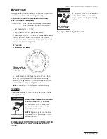
NOTICE
Restraining devices
required.
Figure 2-1
Leveling Griddle
Summary of Contents for miraclean 2000 series
Page 14: ...keatingofchicago com 12 208 240 VOLT WIRING DIAGRAM 3 PHASE CONNECTIONS...
Page 20: ......
Page 21: ......


