


|
keatingofchicago.com
10
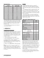
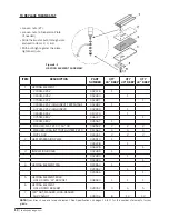
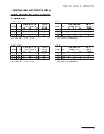
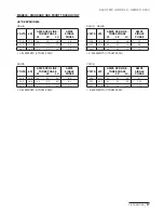
ITEM
DESCRIPTION
PART
NUMBER
QTY
24" DEEP
QTY
30" DEEP
QTY
33" DEEP
1
HEATING ELEMENT
2300W, 220V
002478
1
3000W, 220V
002483
1
3750W, 220V
002487
1
3300W, 220V (HIGH INPUT, TEPPANYAKI)
002482
1
4370W, 220V (HIGH INPUT)
002480
1
3000W, 440V
013270
1
3750W, 480V
006337
1
3300W, 480V
005567
1
WASHER, FLAT, #10 7/16" OD
059502
2
2
2
WASHER, LCKG INT TOOTH HI-TEMP #10
011562
4
4
4
NUT 10-32
000361
2
2
2
2
HEAT DISPERSION PLATE
005913
1
006228
1
006229
1
3
INSULATION BOARD
002489
1
002493
1
002490
1
4
HEATING ELEMENT PAN
020553
1
020554
1
020556
1
5
HEATING ELEMENT BULB
HOLD DOWN “M” BRACKET
008593
1
1
1
6
HEATING ELEMENT
HOLD DOWN BRACKET
029352
3
4
5
7
3/8" NUT, WASHER, LOCK-WASHER
AND PALNUT
028736
8
10
12
NOTE:
Quantities shown are for each element. See Specifi cations on pages 15 to 17 for the number of elements for your
griddle.
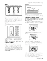
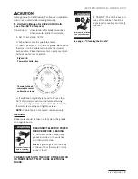
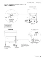
TO REPLACE THERMOSTAT
•
Loosen nuts (#7)
•
Loosen nuts to Dispersion Plate
(if needed)
•
Slide thermostat bulb through slots
pictured in items 2, 3, & 4.
•
With bulb tight against the plate,
tighten all nuts.
Figure 6-3
HEATING ELEMENT ASSEMBLY
Summary of Contents for miraclean 2000 series
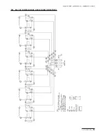
Page 14: ...keatingofchicago com 12 208 240 VOLT WIRING DIAGRAM 3 PHASE CONNECTIONS...
Page 20: ......
Page 21: ......


