background image

6

THERMOSTAT REPLACEMENT KIT (PART #057138)

MOUNTING AND WIRING INSTRUCTIONS

New Thermostat Mounting and Wiring Instructions

1.

After removing the old thermostat, drill four larger holes for
mounting new housing 

(See Figure A)

. After drilling holes,

remove any metal filings from inside the unit.

2.

Feed the female ends of the four new wires from the inside
to the outside of the unit through the old thermostat’s
mounting hole.

3.

Connect the male ends of the four new wires to the female
ends of the wires that came off the old thermostat (L1, L2,
COM. and N.O.).

4.

Feed the new sensor wire through the old thermostat’s
mounting hole.

5.  Remove the two spade connectors that are attached to

the unit thermostat’s sensor wire.

6.

Strip 3/8” of insulation from each of the four ends of the
thermostat’s sensor wires.

7.

Place shrink tubing on both leads of the thermostat’s
sensor wire.

8.

Attach the two pairs of thermostat wires using butt
connectors 

(See Figure C wiring diagram on reverse)

.

9.

Shrink the tubing over the butt connectors on the
thermostat’s sensor wire.

10. Mount new housing to the control panel.
11. Connect all six wires to the new thermostat 

(See Figure C

wiring diagram on reverse).

12. Place the new thermostat in the housing and tighten the

four screws 

(See Figure B)

.

New thermostat Operating Instructions
Operating

When the thermostat is powered up, the display will show
the set operating temperature. To change the operating
temperature, push and hold the “PUSH TO SET” button
and turn the adjustment knob until the desired temperature
is displayed. Release the button to lock in the setting.

Temperature offset

To change the offset, power off the unit. Push and hold the
“PUSH TO SET” button, re-apply power to the unit while
still holding the button down. Turn the adjustment knob to
the desired amount of offset, release the button to lock in
the setting.
Adjust the setting to a positive number if the cooker’s
temperature is higher than the set temperature. Adjust the
setting to a negative number if the cooker’s temperature is
lower than the set temperature.

Figure A:

Location of old thermostat mounting hole and where new holes
should be drilled.

Figure B:

New Thermostat Housing and Control Panel

Summary of Contents for Cooktop

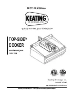
Page 1: ...KEEP THIS MANUAL FOR TRAINING NEW PERSONNEL Keating Of Chicago Inc 1 800 KEATING www keatingofchicago com SERVICE MANUAL TOP SIDETM COOKER manufactured years 1998 2004...

Page 2: ...n 2 Cleaning Procedures 2 3 Cleaning the Cooking Head 3 SECTION IV MAINTENANCE Warranty Repairs 3 Preventive Maintenance 3 4 Installing a Cooking Sheet 4 Handling Cooking Sheets 4 Leveling of Cooking...

Page 3: ...rves the right to change specifications at any time ii FOR YOUR SAFETY DO NOT STORE OR USE GASOLINE OR OTHER FLAMMABLE VAPORS OR LIQUIDS IN THE VICINITY OF THIS OR ANY OTHER APPLIANCE WARNING IMPROPER...

Page 4: ...OUS BURNS OR OTHER INJURIES MAY RESULT IF SAFETY INSTRUCTIONS ARE NOT FOLLOWED DO NOT SUBMERGE THE TOP SIDETM COOKING HEAD IN WATER CLEANING CHEMICALS OR UTENSILS USED FOR CLEANING GRIDDLES WILL DAMAG...

Page 5: ...o ON position 2 Set thermostat to desired temperature Red ELEMENT ON light will illuminate when the element is on Figure 3 1 Top SideTM Cooker Control Panel pre 2005 model Maximum thermostat setting 5...

Page 6: ...IDE COOKING HEAD ARE A DAMP SOFT COTTON CLOTH AND A KEATING SCRAPER NEVER USE A GRIDDLE STONE BRICK GRIDDLE SCREEN OR HARSH CHEMICALS TO CLEAN THE MIRACLEAN SURFACE DAMAGE DONE TO THE MIRACLEAN SURFAC...

Page 7: ...y The time to change a Cooking Sheet is when Product starts sticking to the sheet Too much carbon build up causes a product appearance cooking or taste problem The head surface is cool If the sheet is...

Page 8: ...ON light is faulty a Replace ELEMENT ON Iight not come on but cooking Element on light is part of the head does heat thermostat ELEMENT ON light a Thermostat temperature probe a Replace probe and or...

Page 9: ...r the butt connectors on the thermostat s sensor wire 10 Mount new housing to the control panel 11 Connect all six wires to the new thermostat See Figure C wiring diagram on reverse 12 Place the new t...

Page 10: ...7 Figure C Wiring Diagram Part 056840...

Page 11: ...er Limited Warranty for complete service and ordering information The model serial plate for each cooking head is located on the the control panel assembly The serial and model numbers are necessary w...

Page 12: ...1 028519 26 FRONT PLUNGER 1 028521 27 REAR PLUNGER NOT SHOWN 1 028522 28 TEFLON WASHER NOT SHOWN 1 028490 29 FIBER WASHER NOT SHOWN 2 028500 30 TOP SIDE COOKER WELD MANUAL 1 052114 31 TOP SIDE COOKER...

Page 13: ...ING BRACKET 1 016654 6 CONTACTOR 50A 3 POLE 1 011184 7 ROCKER SWITCH LIGHTED ON OFF 1 016689 8 INSTRUCTION PLATE ON OFF SWITCH PLATE 1 016672 9 INDICATING LIGHT ELEMENT ON RED 250V 1 036933 10 INSTRUC...

Page 14: ...11 VII WIRING DIAGRAM TOP SIDETM COOKER WIRING DIAGRAMS...

Page 15: ......

Page 16: ..._____________________________________________________________________________________ ADDRESS ______________________________________________________________________________________________________ CIT...

Reviews: