5
TABLE 3 – SUMMARY OF CONTROL OPERATION
Quadrant
Type of
Operation
Motor Rotation
Direction
Motor Torque
Direction
Applied Load
Direction
I
Motoring
CW
CW
CCW
II
Regeneration
CCW
CW
CCW
III
Motoring
CCW
CCW
CW
IV
Regeneration
CW
CCW
CW
B. Torque Control Mode –
When Jumper J7 is set to “TRQ” position, the KBRG will vary
motor torque. The KBRG has been redesigned and now contains two (2) types of torque
characteristics which are selectable with jumper J8. Speed/Linear Torque (S/LT) and Non
Linear Torque (NLT). In the “S/LT” position (factory setting), both output torque and
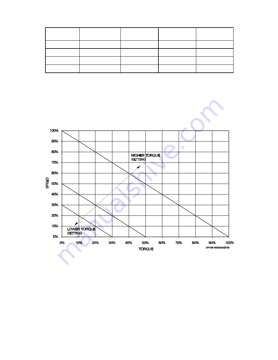
motor speed vary linearly as a function of the input signal. The “S/LT” type of torque is
most suitable for take up and pay out winders where the speed and torque requirements
vary as the winder roll diameter changes. The “S/LT” torque characteristics are shown in
fig. 2A.
FIG. 2A – LINEAR TORQUE CURVE
In the “NLT” position, only torque (not speed) is varied by the input signal. The motor
output torque remains constant over the motor’s full speed range unless the load is less
than the set torque. If the load torque decreases below the set torque, the motor will
rapidly increase to full speed. This type of torque control is applicable to processes where
the torque must remain constant over a wide motor speed range. The “NLT” torque
characteristics are shown in fig. 2B p. 6.
Because the KBRG is a regenerative control, torque will be applied in both forward and
reverse directions. The maximum torque can be set with the FWD CL and REV CL
trimpots, and by using the FWD ACCEL and REV ACCEL trimpots, the rate of change of
torque can be made more or less gradual. The maximum speed trimpot can be used to
set the maximum motor speed under a no load condition.


