background image

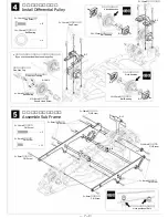
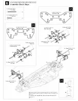
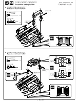
ダンパーステーの組立と取付

Assemble Shock Stays

3×25mmサラビス

                F/H Screw

3×25mmサラビス

                F/H Screw

フロントダンパーステー

Front Shock Stay

リアダンパーステー

Rear Shock Stay

3×25mmサラビス

                F/H Screw

3×25mmサラビス

                F/H Screw

×8

3×10mmキャップビス

                Cap Screw

3×10mmキャップビス

                Cap Screw

3×10mmキャップビス

                Cap Screw

×4

B-5

B-5

B-6

B-4

B-4

B-6

B-6

B-4

B-6

B-4

B-5

B-5

B-4

B-5

B-6

B-6

B-6

B-6

3×25mmサラビス

           F/H Screw

フロントダンパーステー

 Front Shock Stay

リヤダンパーステー

  Rear Shock Stay

7mm

9mm

※B-4、B-5のかわりにオプションのSV-56 マウントカラーセットを
 使用することができます。取付の際は、高さの違いに注意してくだ
 さい。
※You can use the optional SV-56 Mount collar sets instead of B-4 
 and B-5. 

― 8 ―

Summary of Contents for K0600

Page 1: ...builders should seek advice from experienced builders when assembling this Please follow all safety precautions before operating this model Be careful Motor and speed control can get extremely after...

Page 2: ...2 2 channel R C unit Battery for R C unit Servo Receiver Ni cd battery charger Ni cd Battery Electric Speed Controller 540 540 size motor Side cutters Long nose pliers Screwdriver Modeling knife Hobby...

Page 3: ...parts I I parts G G parts E E parts B B parts H H parts 1 2 3 4 5 6 7 1 2 3 3 4 5 6 6 7 1 1 3 4 5 6 7 7 7 2 1 2 1 2 6 6 3 4 5 1B 1A 3A 8A 8B 8C 7 2 2 3 4 5 6 8 7 1 5 4 7 3B 6B 6A 6D 6C 1 2 3 6 7 4 5 8...

Page 4: ...ngle 2 Caution If you plan to use the saddle pack battery configuration file or sand the edges of the battery slots and insulate your batteries with shrink wrap to minimize the possibility of a short...

Page 5: ...o E 6 Install E 6 finally E 1 E 1 1 4 1 2 Spur Shaft 4 8mm Ball Bearing Spring Pin Spring Pin 1 2 Assemble Center Pulley If you use the center one way pulley If you don t use the center one way pulley...

Page 6: ...ing 4 2 2 20mm Cap Screw 2 20mm Cap Screw 6 Allen Wrench small 2 2 Make two sets Insert cut ends Insert cut ends Note direction of conical spring Note direction of conical spring Apply grease Apply gr...

Page 7: ...ew 3 8mm F H Screw 3 8mm F H Screw 3 8mm F H Screw 3 8mm F H Screw 11 10 15mm Ball Bearing 10 15mm Ball Bearing 10 15mm Ball Bearing 4 Attend direction Note direction Note position of Belt B 3 B 3 B 7...

Page 8: ...H Screw 3 25mm F H Screw 8 3 10mm Cap Screw 3 10mm Cap Screw 3 10mm Cap Screw 4 B 5 B 5 B 6 B 4 B 4 B 6 B 6 B 4 B 6 B 4 B 5 B 5 B 4 B 5 B 6 B 6 B 6 B 6 3 25mm F H Screw Front Shock Stay Rear Shock Sta...

Page 9: ...Screw 2 5 8mm Ball 5 8mm Ball 5 8mm Ball 4 E E Clip E E Clip E E Clip E E Clip 8 S Rod Adjuster S S Rod Adjuster S S Rod Adjuster S 4 4mm Nut C 1 B 01 1 1mm You can chice the optional B 01 Superior Hu...

Page 10: ...Clip E E Clip E E Clip E E Clip 8 L Rod Adjuster L L Rod Adjuster L L Rod Adjuster L 4 7 5mm About 7 5mm C 5 C 5 C 1 C 1 3 14mm C 4 F 7 Universal Driveshaft 5 10mm Ball Bearing 5 10mm Ball Bearing 5...

Page 11: ...m Spring rate g mm 1 2 Cover the shaft with cloth to protect O 2 If you install two optional O ring you will be free trouble of front one way O O Ring I 2 I 7 I 4 I 3B Wide Fine Narrow Thick Points To...

Page 12: ...F 7 F 7 3 14mm F H Screw 4 3 10mm Cap Screw 4 For front For rear 64mm Total length 62mm Total length Use the inside hole 3 14mm F H Screw 3 14mm F H Screw 3 10mm Cap Screw 3 10mm Cap Screw Don t brea...

Page 13: ...l Steering Horn Steering Post Steering Post 3 14mm F H Screw 3 14mm F H Screw 3 14mm F H Screw 3 8mm F H Screw 3 8mm F H Screw 5 8mm Ball 5 8mm Ball 5 8mm Ball L Rod Adjuster L L Rod Adjuster L L Rod...

Page 14: ...ntains molybdenum They are precision made and maintain an excellent gear mesh with very low friction 64Pitch Tapered Pinion Gears Optional Tapered Pinion Gear are Nickel plated These are so strong and...

Page 15: ...w 4 Hook Pin Hook pin Hook pin 4 3 8mm F H Screw 4 Hook Pin Hook Pin Hook Pin 4 Assemble battery holder F 10 F 2 F 2 F 2 F 2 Cut Cut Cut Cut Cut If you use a stick type of battery If you use a saddle...

Page 16: ...l 2 I 8C L I 8C Plastic parts for Shock or Rod Adjuster L I 8C I 8C 2 Assemble Servo Saver F 6 F 6 F 5 F 6 F 5 F 5 Choose the appropriate parts to fit your Servo Choose for your Servo F 9 F 9 H 2 H 5...

Page 17: ...3 8mm F H Screw 3 8mm F H Screw 3 8mm F H Screw 2 Install Servo Electronic Speed Controller and Receiver Double sided Tape Double sided Tape Double sided Tape Electronic Speed Controller Receiver Refe...

Page 18: ...3 10mm Cap Screw 1 3 8mm F H Screw 3 8mm F H Screw 3 8mm F H Screw Graind 6 Install Bumper G 5 G 1 G 2 G 3 G 4 If you use a transponder Antenna Pipe White Run a antenna wire through antenna pipe Doub...

Page 19: ...mpound and have a new rounded form They are both high grip and long lasting TU 85i VX Mid TU 86i VR Mid TU 87i 8 Mid TU 88i 6 Mid TU 32M Mid LM35 TU 33 Mid L30 TU 33M Mid LM30 TU 34M Mid LM27 TU 31SS...

Page 20: ...67 5 54 5 42 5 30 5 18 5 07 4 96 4 86 4 77 4 67 4 58 104 5 31 5 20 5 08 4 97 4 87 4 77 4 68 4 58 4 50 102 4 98 4 88 4 78 4 68 4 59 4 50 4 41 100 4 68 4 59 4 50 4 41 4 32 98 4 41 4 32 4 24 Spur Gear Pi...

Page 21: ...SV 10 1 2 2 1 0 mm EZ 2 0 0 FD Floating Disc FD 2mm 1 2 SV 10 3mm C 6 B 4 3 25mm 1mm 6A 1mm 6A 300 400 SV 55 0 1 0 2 4 0 1 2 3 5 7 0 1 2 21...

Page 22: ...130 SV 50a 1800 130 SV 50b 1300 130 SV 51 SV 10 600 130 SV 52 1200 130 SV 53 3200 190 SV 54 550 130 SV 55 1100 3200 3200 3400 130 SV 56 600 130 SV 57 130 SV 58 C 5 130 SV 59 130 SV 150 4200 130 SV 15...

Reviews: