background image

1 – 24

SAFETY

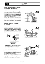
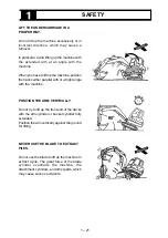
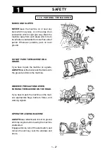
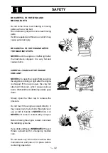
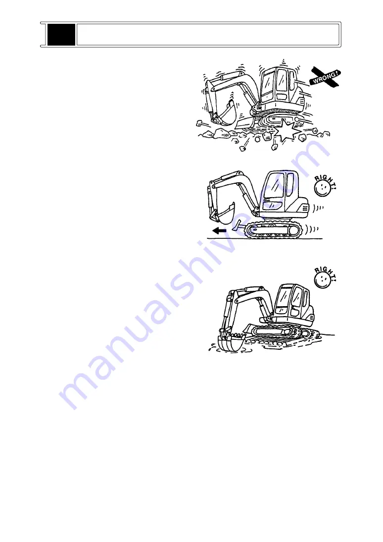
SLOWLY TRAVEL THE MACHINE IN

SPECIAL CONDITIONS.

Travel slowly when the ground is rough or

covered with chunks of rock. Control the travel

speed with the engine throttle lever.

NEVER

 cause shocks to the tracks and the

machine.

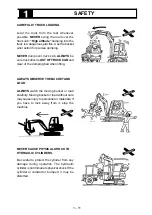
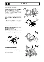
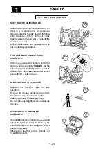
POSITION THE DRVIE SPROCKET TO

THE RIGHT POSITION.

ALWAYS

 travel with the drive sprocket to rear.

Keep the drive sprocket to rear in long travel

in particular. If you position tt to front, wear at

the lower structure will be enhanced.

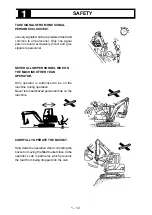
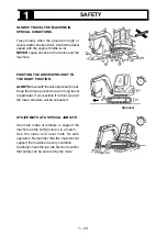
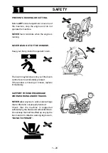
UTILIZE MATS AT A SPECIAL JOB SITE.

Use mats made of lumbers to support the

machine on the soft ground or in a marsh.

Use the clean and level mats for safe

operation. Remember that the mats cannot

support the machine in every condition.

Carefully check the job site first and confirm

that safety can be secured by the mats.

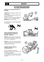
Sprocket

Summary of Contents for 17VXE

Page 1: ...OPERATING INSTRUCTIONS MINI EXCAVATOR 17VXE serial numbers from nr EG17 00010 Original instructions 03 17 R00 Code 2030807142 EN ...

Page 2: ......

Page 3: ...to national law 11 Also complies with the provisions noise emission in the environment by equipment for use outdoors directive 2000 14 EC amended by 2005 88 EC and the regulations transposing it into national law Machine category Hydraulic excavator annex I n 20 Conformity assessment procedure followed internal control of production with assessment of technical documentation and periodical checkin...

Page 4: ...ntedirectriz 13 Cumplenlesnormasarmonizadas 14 Direccion Data 15 Nombre 16 Puesto GERMAN Ubersetzung 1 EG KONFORMITÄTSERKLÄRUNG Direktive2006 42 EG NachtragII 1A 2 Hersteller 3 Adresse 4 Technische Datei erstellt von Technischer Leiter KATOIMERS p A 5 Adresse 6 Erklärthiermit dassdieMaschine Kategorie TRANSPORTER 7 Typ 8 Seriennummer 9 InstallierteNutzleitung 10 Konformist mitdeneinschlägigenBesti...

Page 5: ...ivå Garanteradljudeffektnivå 12 Uppfyller villkorensomomnämnsiföljandedirektiv 13 Följandeharmoniseradestandarderhartillämpats 14 Ort Datum 15 Namn 16 Befattning NORSK oversettelse 1 SAMSVARSERKLÆRING ORIGINAL Direktiv2006 42 EF vedleggII 1A 2 Produsent 3 Adresse 4 Tekniskdokumentasjonutarbeidetav TekniskansvarligKATO IMER S p A 5 Adresse 6 Meddetteerklærervi atmaskinkategorien HJULLASTER 7 Type 8...

Page 6: ...understood at first repeat reading it until abilities as an operator are obtained and developed for proper operation Further abilities as an operator outside of descriptions in this manual can be obtained from the experience during normal operations and under proper supervision The illustrations in this manual are used first of all to let you pay attention They do not show all of illustrations in ...

Page 7: ...ERATION 2 1 Nomenclature 2 1 2 2 Controls and Instruments 2 2 2 3 Before Starting the Engine 2 12 2 4 Starting Engine 2 13 2 5 Jumper Cable Starting 2 14 2 6 After Starting the Engine 2 15 2 7 Break in Operation 2 15 2 8 Backhoe Operation 2 16 2 9 Operating the Special Attachments and Actuators 2 20 2 10 Traveling the Machine 2 22 2 11 Crawler Extention Retraction 2 26 2 12 Towing 2 27 2 13 Liftin...

Page 8: ...enance and Checks 3 20 3 8 1000 hours Maintenance and Checks 3 24 3 9 2 years Maintenance and Checks 3 27 3 10 Unusual Operating Conditions 3 29 3 11 Long Term Storage 3 32 4 TROUBLE SHOOTING 4 1 Trouble and Remedy 4 1 5 HYDRAULIC SYSTEM DIAGRAM 5 1 Hydraulic System Diagram 5 1 6 ELECTRICAL SYSTEM DIAGRAM 6 1 Electrical Wiring System Diagram 6 1 7 SPECIFICATIONS 7 1 General Specifications 7 1 7 2 ...

Page 9: ...e for predicting every kind of danger in all operating conditions It is the owner or user of the machine who is responsible for ALWAYS paying attention to operate the machine as well as reading and understanding this manual enough to obtain the essential knowledge and skills fundamental to correct machine operation BEFORE inspection operation or maintenance of the machine be sure to read and under...

Page 10: ...nd of danger that you may encounter during operation 1 1 GENERAL OBSERVE THE BASICS FOR SAFE AND EFFECTIVE OPERATION The operator s knowledge skills and experience are the most important to utilize the machine Therefore be sure to understand operation procedures and to take necessary training OPERATOR SHOULD BE QUALIFIED Only qualified operators should be authorized to operate the machine and thos...

Page 11: ...stributor for replacement OPERATOR SHOULD BE IN GOOD HEALTH Operator should be physically and mentally alert which is one of the best insurance against an accident NEVER operate the machine under the influence of alcohol medication or intoxication WEAR PROPER WORKING CLOTHES Wear working clothes that closely fit operators Avoid loose jackets shirt sleeves rings and other jewelry which may be caugh...

Page 12: ...rk day just because it seemed satisfactory at the end of the previous work day Before beginning each days operation thoroughly inspect the entire excavator for signs of vandalism MAKE A WORK PLAN Prior to operation investigate your job site sufficiently When any obstruction or hazards are detected mark it so that all personnel are aware of it Avoid any oversight that may cause serious accident Obs...

Page 13: ...the ground ventilation depth of water and ambient obstructions Avoid operating your equipment too close to an overhang Since this machine is not provided with anti explosion design NEVER use it inside a tunnel or in explosive environment to avoid hazard caused by an explosion CLEAR ALL PERSONNEL FROM THE MACHINE AND AREA Be sure to barricade the job site to prevent entry of the unauthorized Confir...

Page 14: ... drilling or cutting can weaken the structure and reduce the protection it provides A damaged ROPS TOPS can not be repaired it must be replaced 1 2 MOUNTING AND DISMOUNTING CAREFULLY MOUNT AND DISMOUNT THE MACHINE ALWAYS use steps and handholds to mount and dismount the machine Hold the handholds with both hands and face the machine keeping a contact with at least three points of the steps and han...

Page 15: ...orn parts Fasten the seat belt if equipped securely Adjust the operator s seat to be able to depress the pedal completely 1 4 STARTING THE ENGINE Fasten the seat belt Adjust the operator s seat ALWAYS start the engine only from the operator s seat following the starting procedure in this manual When the start switch or controls are tagged with Do Not Operate do not start the engine or move any of ...

Page 16: ...etected immediately report it CONDUCT WARM UP BEFORE OPERATION It is ESSENTIAL to conduct warm up operation after starting the engine in order to run the hydraulic fluid smoothly The pumps may squeak because of the cold and thick hydraulic fluid which results in the damage to the pumps ALWAYS take a time to warm up the fluid with running the engine at a low speed to maintain the FREE FLOW OF OIL B...

Page 17: ...on ALWAYS consider the machine capacity and take a time to clear problems in the best way OBSERVE THE NEXT PRECAUTIONS FOR SAFE OPERATlON Do not read Do not drink Do not eat Do not be distracted If you have to divert yourself from the machine operation stop the operation first ALWAYS OPERATE THE MACHINE ONLY FROM THE OPERATOR S SEAT NEVER attempt to operate the excavator from any position except t...

Page 18: ...may require a greater distance for safety Treat all lines as energized NEVER LEAVE LOAD SUSPENDED IN THE AIR NEVER leave the load suspended in mid air when the machine is out of service or you have to leave the machine ALWAYS put down the bucket or load onto the ground Should a malfunction occur it could fall striking equipment or personnel Should contact occur stay on the machine until the boom i...

Page 19: ...NT OR THE LOAD PROVIDE ADEQUATE TAILSWING CLEARANCE Confirm that there is a sufficient clearance around the machine for swinging operation The operator tends to be unconscious of the area behind the machine Before tailswing make sure that there no personnel or objects in such area ALWAYS check for personnel or objects around the machine before swinging NEVER SWING OVER PERSONNEL Be sure that no pe...

Page 20: ...OF TRUCK CAB and clear of the dumping bed when lifting ALWAYS OBSERVE THE BUCKET AND LOAD ALWAYS watch the moving bucket or load carefully Moving bucket or load without care may cause injury to personnel or materials If you have to look away from it stop the machine NEVER CAUSE PHYSICAL SHOCK TO HYDRAULIC CYLINDERS Be careful to protect the cylinder from any damage during operation The hydraulic c...

Page 21: ...o personnel NEVER ALLOW PERSONNEL RIDE ON THE MACHINE OTHER THAN OPERATOR Only operator is authorized to be on the machine during operation Never let unauthorized personnel ride on the machine CAREFULLY OPERATE THE BUCKET Slow down the operation when controlling the bucket or moving the filled bucket close to the operator s cab in particular which prevents the load from being dropped into the cab ...

Page 22: ...d wear on the boom arm and bucket DO NOT MOVE THE ATTACHMENTS TO THE EXTREME ENDS OF THE STROKE If the rod is extended to the stroke end of the cylinder the shock applies a large force to the cylinder which may cause a damage to the boom or arm Operate the machine without moving the cylinder to the extreme end of the stroke It is recommended to operate the attachments near the stroke end of the cy...

Page 23: ...he machine MEASURE DEPTH OF WATER AND CHECK CONDITIONS OF RIVERBED BEFORE FORDING Before fording measure the depth of water and check the riverbed for holes bumps and any dangerous condition by following the next Measure the depth of water first Stop the machine and swing the bucket under the water to detect any bump or obstacle Lower the bucket to measure the depth of water and detect holes occas...

Page 24: ...s at an angle to the ground or touches the ground partially it may be damaged or loose its balance To avoid this level the ground first Do not use the blade to excessively raise the tracks Lower the blade only within a range where the tracks behind the blade lift slightly to ground the blade as a stabilizer MAINTAIN A CORRECT BLADE POSITION lf you need to conduct the deep digging with the blade do...

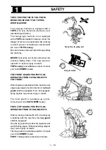
Page 25: ...tion Consult your local lHlMER dealer THE FRONT GUARD PROTECTS AN OPERATOR FROM FLYING OBJECTS THE FRONT When braking materials with the machine and objects are likely to fly from the front the front guard shall be equipped If it is not equipped flying objects may cause injury or death The front guard is avoidable as option Consult your locaI KATO IMER dealer FOPS TOP GUARD PROTECTS AN OPERATOR FR...

Page 26: ...ty prior to operation BE CAREFUL TO PREVENT TURNOVER The operating radius should be as small as possible when using the heavy bucket and swing the boom slowly to prevent a turnover Also watch for buried objects during digging operation to prevent a turnover AVOID UNDERCUTTING THE MACHINE Do not try to dig close to the machine lf you undercut the machine the footing may easily collapses Recede from...

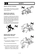
Page 27: ... the width of each track is shorter than its length stability is poorer over side than on the blade side On a grade operate the machine slowly with the retracted arm in a reduced working radius OBSERVE PRECAUTIONS WHEN OPERATING WITH LONG ARM Observe the following precautions to use the long arm c Do not use any combination of arm and bucket that we do not specify d Do not use the breaker attachme...

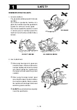
Page 28: ...ious accidents like a turnover 2 Use of attachment c When using the longer arm great care should be taken If tends to reduce the machine stability and limits the bucket size Slowly operate the machine with the longer arm and watch the ground condition d When using the larger bucket great care should be taken It tends to reduce the machine stability Slowly operate the machine with the larger bucket...

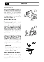
Page 29: ...Lifting capacity in excavators is usually determined by hydraulic and structural fitness not tipping load Before making a list ALWAYS consult the load rating chart in the operator s cab Stay within the lifting limits when laying pipes Remember you may be able to lift the pipe close in at ground level but as you reach out and down the lifting capacity decrease If the machine is not on level ground ...

Page 30: ... tracks either parallel with or at right angle with the machine POSITION THE ARM VERTICALLY Do not try to lift up the front end of the tracks with the arm cylinder or bucket cylinder fully extended Position the arm vertically against the ground for lifting NEVER USE THE BLADE TO EXTRACT PILES Do not use the blade to lift up the machine to extract a pile The great force of the blade cylinder overlo...

Page 31: ... on the alert for overhead obstacles and be sure there is adequate side clearance when traveling Get the assistance of the man on the ground when clearances cannot be ascertained from the operator s position CAREFULLY TRAVEL THE MACHINE IN A NARROW AREA AND LOW CLEARANCE NEVER travel in an area where persons are coming and going or there are many objects ALWAYS keep a safety distance around the ma...

Page 32: ...to the ground and slowly travel When traveling uphill or on a slope keep the boom on the uphill side of the machine NEVER STEER ON A GRADE NEVER steer on a grade or unstable ground which causes a turnover NEVER travel across a grade When traveling on a grade travel up and down in parallel with the grade Be careful to travel on the frozen ground since the machine tends to skid or fall down CHECK BR...

Page 33: ...avel with the drive sprocket to rear Keep the drive sprocket to rear in long travel in particular If you position tt to front wear at the lower structure will be enhanced UTILIZE MATS AT A SPECIAL JOB SITE Use mats made of lumbers to support the machine on the soft ground or in a marsh Use the clean and level mats for safe operation Remember that the mats cannot support the machine in every condit...

Page 34: ...up by itself a wire rope should be attached to the rear axle and the machine should be towed by a towing machine NEVER attach the wire rope to the towing hook at the rear axle which causes damage to the axle and the hook and personal injury may occur USE THE TOWING HOOK PROPERLY The towing hook is used to tow for lightweight material The maximum allowable towed weight is 500kg NEVER tow the machin...

Page 35: ...ing and unloading NEVER LOAD AND UNLOAD THE MACHINE WITHOUT RAMPS TO PREVENT TURNOVER NEVER lift up the machine using the boom to load and unload the machine on and out of the truck This is very dangerous ALWAYS ensure that a ramp has sufficient strength and length to accommodate the size and weight of the machine OBSERVE PRECAUTIONS ON TRANSPORTATION Be sure to engage the swing lock Block tracks ...

Page 36: ... PARK THE MACHINE ON A GRADE If you have to park the machine on a grade ALWAYS lower the bucket and the blade onto the ground and block the machine OBSERVE PRECAUTIONS WHEN PARKING THE MACHINE ON THE ROAD If you have to park the machine on the road use appropriate flags barriers flares and warning signals OPERATOR LEAVING MACHINE ALWAYS lower attachments to rest on ground and stop engine before le...

Page 37: ... controls should be TAGGED the tag should be removed only by someone who is aware of the circumstances and who can assure that it is safe to do so ALWAYS CLEAN THE MACHINE Maintain the machine clean for safe operation Remove dirt grease maintenance tool from the operator s cab for secured control Clean the window to obtain good sight Do not place anything flammable around the machine SET HYDRAULIC...

Page 38: ... cab The boom may fall down onto you if the boom control lever is accidentally pressed If the window is missing or broken replace immediately SUPPORT THE UNDERCARRIAGE WHEN WORKING UNDER TRACKS NEVER allow anyone to work undercarriage that is lifted and not properly blocked Check that the machine is supported sufficiently by the blocks and will not fall down Do not keep the machine lifted up only ...

Page 39: ...after handling Battery acid will burn skin eat holes in clothing and cause blindness if splashed into eyes If you spill acid on yourself flush skin immediately with lots of water Apply baking soda to help neutralize the acid If acid gets in your eyes flush immediately with large amount of water and seek proper medical treatment immediately When servicing battery remember that a lead acid storage b...

Page 40: ...nd that lines pipes and hoses are in good condition before starting the engine Fluid escaping from a small hole can be almost invisible Use a piece of cardboard or wood instead of your hands to search for suspected leaks If you are struck by escaping hydraulic fluid under pressure serious reactions can occur if proper medical treatment is not administered immediately NEVER WATCH THE RELIEF VALVE W...

Page 41: ... the engine is running or right after the engine is stopped lf the cap is open the very hot steam will blow out which causes serious burns Wait until the coolant temperature goes down Slowly open the filler cap to release the pressure Do not touch the engine coolant directly It may cause injury to your skin Wear gloves or use a cloth to handle it NEVER drink it or NEVER let it come in contact with...

Page 42: ...sure that you can read all safety signs Clean or replace these if you cannot read the words or see the pictures When cleaning the labels use a cloth water and soap Do not use solvent gasolin etc You must replace a label if it is damaged missing or cannot be read If a label is on a part that is replaced make sure a new label is installed on the replaced part See your IHl dealer new labels Located w...

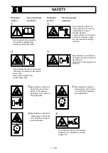
Page 43: ...ower working device to locke position and remove engine key with you before leabing machine d e f Sign indicates a crush hazard by rotation of upper structure of the machine Keep away frrom swing area of machine gSign indicates a hazard of being hit by the working device of the machine Keep away from machine during operation hSign indicates a hazard of rotating parts such as belt Turn off before i...

Page 44: ...ator or hydraulic tank to cool before removing cap Sign indicates a hazrd of flying plug from track adjuster that could cause injury Read manual before adjusting track for safe and proper handling 12 DANGER Attach a DO NOT OPERATE warbubg tag ti start switch or controls before servicining or repeairing the machine Do not start the engine or move any of the controls if their is DO NOT OPERATE or si...

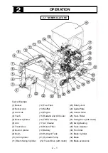
Page 45: ...g Cylinder 12 Fuel Tank 13 Muffler 14 Engine 15 Radiator and Oil Cooler 16 TOPS Canopy 17 Air Cleaner 18 Return Filter 19 Battery 20 Hydraulic Tank 21 Hydraulic Pump 22 Travel Drive with motor 23 Rotary Joint 24 Guide Plate 25 Control Valve 26 Track Roller 27 Swing Drive with motor 28 Swing Bearing 29 Track Adjuster 30 Front Idler 31 Blade Cylinder 32 Blade 33 Blade extensions ...

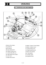
Page 46: ...ver 19 Boom Swing Pedal 20 Travel pedals 21 Auxiliary pedal 22 Operator s Seat 6 Service Hour Meter 7 Light Switch 8 Horn Switch 9 Engine Start Switch 10 Engine Throttle Lever 11 Control Shut Off Lever 12 High Speed Travel Switch 13 Left Travel 14 Right Travel Lever OPERATION 2 2 CONTROLS AND INSTRUMENTS ...

Page 47: ...oil pressure Check the engine oil level and have any necessary repairs made before starting the engine d Charge Warning Lamp This indicates a malfunction in the electrical charging system If the light comes on while the engine is running check the electrical system e Quick GIow Lamp This lamp indicates preheating status of the engine in its starting period It lights when the start switch is turned...

Page 48: ... running the engine with out load and low idling warming up The Green range is the normal operating temperature The Red range indicates overheating If the gauge indicate red range reduce machine operating speed and keep the engine at low idle until the engine is cooled down Stop the engine Check the coolant Check the fan drive belt Have any necessary repair made h Service Hour Meter Indicates the ...

Page 49: ...the OFF position to stop the engine ON Turn the key clockwise to active the electrical System The key will return to the ON position when released from the START position START Turn the key to the START position to crank the engine Release the key as soon as the engine starts HEAT If the engine is hard to start in cold weather hold the switch in the HEAT position to preheat the engine intake air A...

Page 50: ...aulic activation contorols inoperable Unlocked Move the lever forward to the unlocked position This makes all hydraulic activation controls operable 12 High Speed Travel Button NEVERhighspeedtravelonagradeor loading and unloading the machine When control shut off lever is locked does not change to high speed travel Low Speed Travel Release the button to low speed travel Select the LOW speed travel...

Page 51: ...ersed Always travel with sprockets under the rear of the machine Forward Direction Travel Move the both travel levers forward to move the machine forward direction Stop Release the travel levers to stop the machine and apply the brakes Reverse Direction Travel Move the both travel levers rear to move the machine reverse direction Refer to Traveling the Machine section of this manual CAUTION SPROCK...

Page 52: ...l the spanner blade lever Crawler retraction backward With the green Blade Spanner Control Button pushed Release the button to selected Spanner operations Spanner operations modality Push the button to selected Arm Out 1 Swing Right 3 Arm In 2 Swing Left 4 Hold 5 ISO System 17 Left Operating Lever TYP A ISO Lever Swing and arm controls 1 Arm Out Move the lever forward 2 Arm In Move the lever rear ...

Page 53: ...on the lever will return to hold center position Boom or bucket movement will stop Boom Lower 1 Bucket Dump 3 Boom Raise 2 Bucket Dig 4 Hold 5 ISO System 18 CAUTION Boom Swing Pedal ALWAYS locked pedal when is not in use Boom swing right Push down right on the pedal to swing the boom to the right Boom swing left Push down left on the pedal to swing the boom to the left 19 The bucket and boom funct...

Page 54: ...d position to allow full pedal and lever travel To Adjust the Seat Forward or Backward Pull up and hold lever 2 and move the seat to the desired position Release the lever to hold the seat in the selected position To Adjust the Seat Back Tilt Turn knob 3 clockwise to tilt the seat back to backward Turn knob 3 counter clockwise to tilt the seat back to forward To Adjust the Seat Suspension Turning ...

Page 55: ...worn or damaged buckle extrusion and mounting hardware Replace them if they worn or damaged To Fasten the Belt With gripper c held and insert extrusion d into buckle e until correctly latched Adjust the seat belt length according to your body size Slightly pull the belt fand confirm the belt is fastened To Unfasten the Belt Push in button gof buckle eand extrusion dwill be released from buckle e C...

Page 56: ... area and cylinder mounting brackets Repair if damaged Refer to Walk Around Inspection in the Maintenance Section Lubrication Perform the daily lubrication as required by the Lubrication Chart Pre start Checks Check all of oil coolant and fuel levels Refer to the Daily in the Maintenance Section for more detailed information Seat and Seat Belt Checks Adjust the seat to allow full travel of the lev...

Page 57: ...the starter to cool for seconds before cranking again 6 Release the switch key after the engine starts 7 Move the engine throttle lever to position LOW to allow the engine to warm Starting In Cold Weather This engine has an inlet manifold heater for cold weather starting Do not use other types of starting aids such as ether Such use could result in an explosion and personal injury 1 Repeat steps 1...

Page 58: ...d Move all controls to HOLD Stop the engine on boost machine 3 On stalled machine turn the start switch key to OFF Turn of all accessories WARNING 4 Connect POSITIVE jumper cable red POSITIVE cable terminal of discharged battery Do not allow positive cable clamp to touch any metal other than battery terminals 5 Connect POSITIVE jumper cable red POSITIVE cable terminal of boost battery 6 Connect on...

Page 59: ...ve minutes while intermittently holding the bucket control lever in the bucket dump position Operate the bucket control lever for 10 to 15 seconds and then return the control lever HOLD position to ten seconds 3 Move the engine throttle lever to maximum engine speed Run the engine for an additional five minutes while intermittently holding the bucket dump position This will allow the oil to reach ...

Page 60: ...ECTTON OF MACHINE BOOM BUCKET ARM SWING When leaving the operator s seat stop the engine lower the bucket and the blade on the ground Lower Operating lever R H Raise Dump Operating lever R H Dig Operating lever L H Out In Operating lever L H Swing right Swing left Swing right Swing left Lower Raise Dump Dig Out In ...

Page 61: ...ATTERN F Bucket and arm controls 1 Arm Out Move the lever forward 2 Arm In Move the lever back 3 Bucket Dump Move the lever right 4 Bucket Dig Move the lever left 5 Hold When the lever released from any position the lever will return to hold in center position The bucket and boom functions can be operated together For example to move out the boom and dump the bucket at the same time push the lever...

Page 62: ...2 1 8 ...

Page 63: ...cked position Swing R H Swing L H Locked position Boom Swing Pedal Swing R H Swing L H Boom Lower Raise Blade lever Blade Raise Expansion Blade lever Retraction Spanner selection button Push Expansion Retraction Crawler BACKHOE OPERATION When no breaker operation is needed be sure to lock the pedal ...

Page 64: ... be sure to lock the pedal dby lock lever eto the LOCKED position 2 9 OPERATING THE SPECIAL ATTACHMENTS AND ACTUATORS If equipped Select a hydraulic breaker a wrecking fork and special actuators etc witch are applicable to the machine body Consult your local KATO IMER dealer to select a special attachment and an actuator Precautions on use of special attachment and actuator Before using a special ...

Page 65: ... DOUBLE ACTION OPERATION Wrench Fork and Others Controls Switching the attachment hydraulic circuit Check the marked position on the shift valve Turn the valve with a wrench and set the marked in horizontal position if necessary 1 Unfold the pedal into two pedal plates 2 Move the lock lever to the unlocked position To actuate the port A Push down on the front of the pedal to actuate the port A To ...

Page 66: ... enough to provide sufficient ground clearance 4 Control right and left travel levers eas follows Forward Direction Travel Move the both travel levers eforward to move the machine forward The machine will always travel toward the BLADE Stop Slowly move both the travel levers e to the stop position to stop the machine and apply the brakes Reverse Direction Travel Move the both travel levers e rear ...

Page 67: ...on the left track Pivot Right Turn Move the left lever dforward to travel forward and right and move it rear to travel reverse and right pivoting on the right track SPOT TURN Spot Left Turn Move the left travel lever drear and move the right lever c forward at the same time This allows a quick left turn Spot Right Turn Move the right travel lever crear and move the left lever dforward at the same ...

Page 68: ...o not change travel speed ranges while going downhill NEVER high speed travel on a grade or loading and unloading the machine When control shut off lever is locked does not shift to high speed travel Push down the high speed travel button c shift to the high speed travel When released button shift to the low speed travel TRAVEL PEDALS Travel levers are equipped of pedals that permit to drive machi...

Page 69: ...pe which could result in tipping or side slipping of the machine Keep the arm in and carry the boom in a low position When starting up a steep grade or breaking over a rise keep the boom lowered as close to the ground as possible 1 Whentravelinguponagradeincliningbygreater than 15º keep the position in the right illustration and travel with a low engine speed 2 When traveling down on a grade incli...

Page 70: ...sometimes impossible Extend or retract the crawler on a level ground without an obstacle Extension or retraction is possible without jacking up the main unit If there is an obstacle on the ground beside the crawler the resistance is larger and extension or retraction is sometimes impossible Extend or retract the crawler on a level ground without an obstacle Extension or retraction is possible with...

Page 71: ...w line angle to a minimum Do not exceed a 30º angle from the straight ahead position 1 If the machine sinks down on a soft ground and cannot crawl up by itself a wire rope should be attached to the rear axle and the machine should be towed by a towing machine To prevent the damage of the wire rope be sure to place a protector at the corner of the axle Use the towing wire rope with sufficient stren...

Page 72: ...achine with the boom swing pedal 4 Stopthe engine 5 Instau the cables to the two lifting eyes on the blade with shackles Install the cable to the lifting eye on the boom of the center with shackle 6 Install the cables to the crane hook 7 Confirm that no obstacles nor personal are around the machine and have the operator leave the machine 8 Once the machine is lifted off the ground check that the m...

Page 73: ...k bed before loading NEVER operate the high speed travel switch when loading the machine on a trailer or loading lamps Perform warm up the machine before loading and unloading under cold weather Do not raise the boom excessively at loading and unloading NEVER make a turn on a ramp To make a turn get off the machine from the ramp first WARNING WARNING MACHINE LOADING ONTO A TRUCK 1 Block the truck ...

Page 74: ... tension increases travel resistance whichpreventspropertravel force and speed it also causes damages and extreme wear at undercarriage as well as overextension of the rubber track shoe 2 To prevent damages of the rubber track shoe avoid the following in travel as much as possible Pointed rocks or quarry Craggy place such as riverbed or path through woods Steel rods or scraps Steel board or corner...

Page 75: ...or the hydraulic system disabled 1 Remove the floor cover under the operator s station floor 2 Remove the lock nut d of the boom raise relief valve located inside the control valve c 3 Slowly loosen adjusting screw e until boom start lower The boom will start to lower slowly 4 After making sure that the front implement has lowered completely on to the ground install the lock nut d 5 Make any neces...

Page 76: ...emperature are expected each crawler frame should be cleaned of mud and dirt and the machine parked on wood planks Engine Stopping 1 Operate the engine at LOW IDLE for five minutes This gives the engine a chance to cool off gradually before they are stopped 2 Turn the start switch key to OFF Remove the key Leaving the Machine 1 Use the steps and handhold use both handles and face the machine when ...

Page 77: ... only to initial period of use Break in Check and Adjust Tension Rubber track shoe mantenance Replace Replace Mantenance Change Bucket Check Oil Level Check Coolant Level Check Hydraulic Oil Level Check Fuel Level Check Service Signal Check Level and Drain Water Drain Water and Sediment Lubricate Fitting with Grease Lubricate Fitting with Grease Change Oil and Finer Change Return Filter Change Oil...

Page 78: ...t Check oil level H z e Hydraulic tank Drain water and sediment Wash and clean strainer f Return filter Change filter z z Change engine oil E z z Change fuel filter z g Engine Change oil filter z z Clean or Change air filter Check coolant level W z h Swing bearing Bearing lubricate with grease G Ring gear lubricate with grease G i Travel drive Check oil level and change z oil L j Blade Lubricate w...

Page 79: ...casion Travel Drives 0 33 liter 1000Hrs API Class CD Each SAE30 Lubricate Swing Bearing EP2 Lithium the Fitting Attachment pins etc Grease Note 1 Oils in the hydraulic fluid columns marked with should be use above 0 ºC 2 If the oil becomes dirty or deterioration of the oil s properties are excessive replace more frequently than described above 3 Disassemble the track roller and upper roller when r...

Page 80: ... In case of steel shoes approximately 30 to 50 mm Track Tightening 1 Add grease through check valve fitting cuntil the correct track tension is reached 2 Move the tracks forward and reverse to equalize the pressure 3 Check the the amount of track sag again and adjust as necessary Track Loosening 1 Remove soil deposited on front idler bearing 2 Loosen the check valve d carefully one turn maximum un...

Page 81: ...damage replace it with brand new one 3 Break of Steel Cords When break of steel cord is detected replace it immediately If you leave it as it is the rubber track shoe can be break without expectation which causes a serious accident 4 Crack of Covering Rubber If a crack is 30 mm or more long and 8 mm or more deep repair the cover immediately if Steel cord appears even if a crack is small repair it ...

Page 82: ...e fuse amperage c Fuel pump Control shut off and Travel speed shift solenoid 10 amps d Horn Lighter plug and Cab dome light 20 amps e Front light 20 amps f Monitor Radio Heater and Wiper 20 amps g Engine stop and QOS timer 30 amps FUSIBLE LINK The fusible link is provided between the positive terminal of the battery and the starter switch to prevent electrical circuit wires from being burned becau...

Page 83: ...ery Recharge Battery should not be allowed to stand in a fully discharged condition but should be recharged as soon as possible If battery is out of use for a long time it must not be allowed to run down completely The battery should be given a small recharge sufficient to bring it back to fully charged state about every one or two months Trickle charging is not recommend and during charging as be...

Page 84: ...andB thenremove the arm and the bucket Install the Bucket 1 CIean the removed pins and pin holes and apply coat the grease to them surface 2 Place a new bucket in a stable position as illustrated 3 Connect the arm into the hole A and the link into the hole B with pins 4 InstaII a stopper bolt to each pin securely 5 Adjust the bucket clearance 6 Move the O rings for sealing into the regular positio...

Page 85: ...il Clean and install the oil fill plug 5 Close the access door Check the Coolant Level Steam generated by hot fluid under pressure in radiator can cause personal injury Remove filler cap only when cool enough to touch with bare hand 1 Open the access door on the rear of the machine 2 Always check the coolant level in the reserve tank Maintain the coolant level between the MAX and MIN marks on the ...

Page 86: ...rize the hydraulic tank refer to Change Hydraulic Oil section Fill Fuel Tank Fuel can be added to the tank by removing the fill cap on top of the fuel tank Do not remove strainer in the fill port when fill fuel tank After completion of refueling be sure to lock the fuel tank cap to protect against vandalism Dust Indicator Check the air filter dust indicator If the indicator is in the red zone clea...

Page 87: ...ner NOTE Always dispose of drained fluids as established by local regulations 5 Clean the inside surfaces of the body and cup 2 6 Clean the filter 3 7 Inspect the O ring 4 Replace it if they are worn or damaged 8 Install a filter 3 to the cup 2 Install a spring 5 and float 6 into the cup 2 Install the cap 2 to the body and tighten ring nut 1 9 Turn the fuel stop lever to the OPENED position 10 Pri...

Page 88: ...amage or excessive wear Repair if damaged Inspect and remove any trash build up in the engine compartment Inspect the cooling system for leaks faulty hose and trash built up Correct any leaks and remove any trash from the radiator Inspect the hydraulic system for leaks Inspect the tank cylinder rod seals tubes plugs joints and fittings Correct any leaks Inspect and repair travel drive leaks Check ...

Page 89: ...NOTE Always dispose of drained fluids as established by local regulations Lubrication Perform the 50 hours lubrication as required by the Lubrication Chart Be sure to lubricate all cylinder mounting bushings and pins The following maintenance and checks should be made in 50 hours for the initial time only Interval given applies only to period of use break in Return filter replacement Engine oil re...

Page 90: ...ove the used filter d by the filter wrench Clean the filter housing base 5 Apply a light coat of engine oil to the gasket of the new filter 6 Install the new filter by hand When the seal contacts the base tighten the filter 3 4 turn more by filter wrench Do not overtighten 7 Remove the oil fill plug e Fill the crankcase with oil Refer to Recommended lubricant table Clean and install the oil fill p...

Page 91: ...lacement After cleaning five times after one year or damaged pleats or seals 1 Stop the engine 2 Release the three latches and remove the service cover c 3 Remove the primary elementdfrom the air cleaner housing e Do not remove the secondary element テ when service the primary element d only NOTE Remove the seal unit of element gently The element is radially sealed by the element seal unit and seal...

Page 92: ...reign substances on the inside and outside of the housing seal tube 7 Install a clean primary element d Install and secure the service cover c with the valve g at the bottom NOTE Insert a new element correctly When the element seal unit is inserted into the seal tube its seal surface is extended uniformly to seal the element To seal the element more accurately push securely not the center but the ...

Page 93: ...ent f from the air cleaner housing e Cover the engine intake opening 3 Clean the inside of the air cleaner housing eand service cover c Remove the covering from the intake opening NOTE Clean the seal tube in the cleaner housing Dust on the seal tube causes dust leak 4 Install the new secondary element f 5 Install the primary element d secure the service cover c 6 Reset the dust indicator hby pushi...

Page 94: ... clean element 8 Inspect the O ring 4 Replace it if they are worn or damaged 9 Install cup 4 on body and tighten ring nut 3 10 Turn the fuel stop lever 2 to the opened ON position NOTE Do not start the engine until all fuel system service is completed Priming the system There should be enough fuel in the system to allow the engine to start Keep the engine start switch key at ON for a period of 20 ...

Page 95: ...lt inward by hand apply 98N 10kg force midway between the pulleys Correctly adjusted belt will deflect 8 12 mm Adjust 1 To adjust the belt loosen mounting bolt c and d 2 Move the alternator in or out as required to obtain the correct adjustment 3 Tighten mounting bolts c and d 4 Check the belt adjustment again after 5 minutes of engine operation at rated speed WARNING Alternator Adjust plate Bolt ...

Page 96: ...s Tighten point Wrench size Thread size Tighten torque metrie mm N m c Traveldrive Bar 8 M10 55 d Sprocket Bar 8 M10 55 e Lower roller 19 M12 108 f Swing bearing 19 M12 108 g Swing motor Bar 10 M12 108 Newrton meter N m is approximately the same as 0 1 kg m 2 General torque specifications Other than above mentioned refer the next table for torques Tighten torque Metric Metric fine coarse H T H T b...

Page 97: ...base d NOTE This is a cartridge type element It cannot be reused 5 Coat the gasket fof new finer with clean hydraulic oil 6 Install the new finer e by hand When the seal contacts the base tighten an additfonal 3 4 turn by filter wrench 7 Start and run the engine to fill the fiPter Stop the engine Maintain the oil Ievel between marks on the level gauge Add oil if necessary 8 Pressurize the hydrauli...

Page 98: ... container NOTE Always dispose of drained fluids as established by local regulations 5 Clean the inside surface of the cup 4 6 Install the new element 5 7 Inspect the O ring 4 Replace it if they are worn or damaged 8 Install cup 4 on body and tighten ring nut 3 9 Turn the fuel stop lever 2 to the opened ON position NOTE Do not start the engine until aIl fuel system service is completed 10 There sh...

Page 99: ...ontact a KATO IMER dealer CAUTION 500HOURS Oil fill plug Oil level plug 1 Position one travel drive with oil drain plug 1 at the bottom 2 Remove the oil level plug 2 and fill plug 3 Oil should be to the bottom of the level plug opening 3 Add oil through the opening of oil level fill plug if necessary 4 Clean the plugs lnstall the plugs 5 Perform procedure on the other travel drive Oil drain plug ...

Page 100: ...evel plug 2 and oil fill plug 3 Allow the oil to drain into a container NOTE Dispose drained material according to local regulation 3 Clean the plugs 4 lnstall drain plug 1 5 Fill the travel drive to bottom of level plug opening 6 Install oil level plug 2 and oil fill plug 3 7 Perform procedure on the other travel reduction 8 Start the engine and allow the travel drive to turn through several cycl...

Page 101: ...rnalpressurefromthehydraulictank by loosening the fill plug c 3 Clean area thoroughly to keep dirt out of strainer cover unit d and fill plug c 4 Remove the oil drain plug e Drain oil into a container Drain oil in all parts of the hydraulic system thereafter NOTE AIways dispose of used oil as established by local regulation 5 Remove the suction hoses f Remove the bolts g and the strainer cover uni...

Page 102: ...aintain the oil level between FULL H and ADD L marks on the level gauge j 15 Pressurize the hydraulic tank Raise the boom with the arm boom and bucket cylinder fully extended Remove the fill plug c and then install fill plug again 16 Lower the bucket on the ground and stop the engine Hydraulic Oil Change Intervals for Breaker Works Hydraulic oil should be changed in every 600 service hours CAUTION...

Page 103: ...to a container 4 Remove the water drain plug 3 allow the coolant to drain into a container Drain plug is located under the injection pump on the front side of cylinder body NOTE Always dispose of drained fluids as established by local regulations 5 Close the drain cock 2 screw the drain plug 3 back on slacken off the bleeder screw 5 and fill the radiator with clean water and detergent 6 Tighten do...

Page 104: ... the freezing point Select the mixing ratio for a freezing point lower by 5º than the expected lowest atmospheric temperature Normally the Long Life Coolant is used under a mixing ratio of 30 to 50 If the mixing ratio is less than 30 occurrence of rust is feared and when it is over 50 overheating is feared and sealing components may be deteriorated quicker than usual Meanwhile use city water to mi...

Page 105: ...stem component found to be defective 2 Condensation in the fuel tank contaminates the fuel supply with water which can freeze in the fuel lines and block the fuel flow to the engine To minimize this possibility keep the tank as full as is practical during cold weather This may entail refilling the tank more frequently than usual but the inconvenience is small compared to clearing a blocked fuel li...

Page 106: ...of coolant will most often be corrected by SLOWLY adding coolant while the engine is running at FAST IDLE Should this fail to correct the problem drain and flush the system and refill with fresh coolant 50 solution of ethylene glycol and a corrosion inhibitor Allow the engine to cool before draining and flushing the cooling system Water containing more than small concentrations of salt or minerals...

Page 107: ... to the deteriorating effects of salt moisture or both To protect exposed metallic surfaces wiring paint and other items keep them dry and well lubricated where salt or high humidity are encountered Follow the recommendations below when operating in these conditions 1 Make frequent inspections for rust and corrosions and remove them as soon as they are detected Dry and paint exposed surfaces after...

Page 108: ...rods Store the battery after move the negative terminal andcoveringitordismountingthebatteryfromthe machine Lock the control levers and pedals with the lock lever and pedal lock During Storage If you have to operate the machine indoors to prevent rust keep good ventilation and gas poisoning by window or entrance During storage operate the machine once a month to maintain films of oil at the lubric...

Page 109: ...ow Control valve damaged Clogging foreign matter such as stone Defective travel motor or reduction Defective brake valve Clogging foreign matter Shoe tension unequal Defective pump Loosen travel lever stopper Defective motor or brake valve Fail lubricate of swing bearing Defective motor Defective brake valve Defective cushion valve Low hydraulic oil Improper viscosity hydraulic oil Main relief val...

Page 110: ...5 1 HYDRAULIC SYSTEM DIAGRAM 5 1 HYDRAULIC SYSTEM DIAGRAM 2 9 30 ...

Page 111: ... 0 75mm Rosso Mar 0 75mm TIMER PULSANTE CLACSON INTERRUTTORE FARO Rosa 0 75mm BOXSIDE M AG Ver Mar 0 75mm G Nero 0 75mm PULSANTE SPANNER SPANNER SWITCH Grigio 0 75mm LIGHTS SWITCH Verde ch 0 75mm AH SWITCH HORN n 2 Gia Marr 0 75mm Arancio 0 75mm N O M AH Gia Mar 0 75mm n 2 Nero 0 75mm Opt F AH Marrone 0 75mm Bia Mar 1 5mm DIODE CONNECTOR Nero 0 75mm Grigio Su boom On boom DIODO DIODE CONN DIODO Bl...

Page 112: ... Rated output kW min 1 ps rpm 10 5 2300 14 3 2300 ISO 3046 1 Max torpue Fuel L 20 Hydraulic Oil level L 19 fluid Total amount L 23 Engine oil Max level L 3 0 Min level L 1 0 Coolant Engine proper L 0 9 Total amount L 3 6 STD with ADD Weight Machine mass Rubber shoe kg 1620 1720 Steel shoe 1680 1780 Average ground bearing Rubber shoe kPa kgf cm2 25 5 0 26 26 5 0 27 pressure Steel shoe 27 5 0 28 28 ...

Page 113: ...ment according to ISO5349 GROUND ACTION Unit Eq ac Driving 1st speed m sec 1 53 Flat and compacted Asphalt Driving 2nd speed m sec 2 39 Digging lowered blade m sec 2 03 Earth Filling m sec 1 77 BUCKET Standard Applicable Not Applicable Combinations Bucket capacity ISO JIS m 3 Widht mm side cutter A Number of teeth Weight kg Standard arm Long arm 0 040 400 4 36 General digging General digging 0 020...

Page 114: ...0 980 980 980 E Canopy 2330 2330 2330 2330 F Rear end swing radius 680 680 720 720 G Rear end ground clearance 460 460 460 460 H Mini ground clearance 175 175 175 175 I Overall length of undercarriage 1950 1950 1950 1950 J Blade height 235 235 235 235 K Blade width 980 1300 980 1300 980 1300 980 1300 L Overall length Blade in front 3380 3380 3380 3380 Blade in rear 3740 3740 3740 3740 M Front end ...

Page 115: ...SPECIFICATIONS 7 7 3 WORKING RANGE OFFSET DIGGING WORKING RANGE Machine with Canopy Front end min radius at right boom swing Front end min radius at left boom swing 7 4 ...

Page 116: ...ot used blade 2100 2350 D Radius of max digging depth 1680 1680 E Max digging height 3610 3810 F Radius of max digging height 1740 1900 G Max dumping height 2560 2760 H Radius of max digging height 1610 1770 I Min dumping height 950 720 J Radius of min dumping height 1350 1440 K Max vertical digging depth 1770 2010 L Radius of max vertical digging depth 2430 2490 M Radius of min digging ground lev...

Page 117: ...ICATIONS 7 7 5 RATED OBJECT HANDLING CAPACITIES TABLE HERE MAY BE SOME LOCAL GOVERNMENT REGULATIONS REGARDING THE USE OF EXCAVATORS TO LIFT HEAVY OBJECTS PLEASE OBSERVE THOSE REGULATIONS WHERE THEY APPLY WARNING ...

Page 118: ...MINI EXCAVATOR 17VXE PUBLISHED MARCH 2017 KATO IMER S p A ITALY ...

Page 119: ......

Page 120: ......

Reviews: