


65
Figure 5.3.15-1
Figure 5.3.15-2
Figure 5.3.15-3
Figure 5.3.15-4
Figure 5.3.15-5
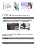
15.10. Pelvic Belt Adjustment for KISS Seat
The pelvic belt is shown as Figure 5.3.16-1.
Use the #5 Allen Key Wrench and the #13 box end Wrench to remove the screw and nut. The pelvic belt can
be installed at point A, B or C. Re-tighten the screw. (Figure 5.3.16-2)
The pelvic belt can also be fixed at slot C to meet the user's needs. (Figure 5.3.16-2) In order to this
replacement, the M8 Phillips Flat Round Head Screw and Nylon Insert Hex Nut have to be replaced by a M6
Phillips Flat Round Head Screw and a Square Nut. (Figure 5.3.16-3, Figure 5.3.16-4)
Figure 5.3.16-1
Figure 5.3.16-2
Figure 5.3.16-3
Summary of Contents for Morgan KISS Seat
Page 2: ...2 release 04 2019...
Page 9: ...9 3 Declaration of conformity Morgan Series...
Page 116: ...116...