background image

9.800-199.0  •  Kärcher Trailer Manual •  Rev. 01/08

9

TRAILER


OPERA

TOR’S MANU

AL


BraKeS

Brake adjustment

Brakes should be adjusted (1) after the first 200 miles 
of  operation  after  the  brake  shoes  and  drums  have 
“seated”, (2) at 000 mile intervals or () as use and 
performance require. The brakes should be adjusted in 
the following manner:
  1.  Jack up trailer and secure on adequate capacity jack 

stands. Check that wheel and drum rotate freely.

  2.  Remove adjusting hole cover from adjusting slot on 

bottom of brake backing plate.

  .  With screwdriver or standard adjusting tool, rotate 

the starwheel of the adjuster assembly to expand 
the brake shoes. Adjust the brake shoes out until 
the pressure of the linings against the drum makes 
the wheel very difficult to turn.

    Note:

 With drop spindle axles, a modified adjusting 

tool with about an 80° angle should be used.

  4.  Then  rotate  starwheel  in  opposite  direction  until 

wheel turns freely with slight lining drag.

  5.  Replace the adjusting hole cover and lower wheel 

to ground.

  6.  Repeat above procedure on all brakes.

CAUTION:    Never  crawl  under  your  trailer 
unless it is resting on properly placed jack 
stands.

Do not lift or place supports on any part of the suspen-
sion system.

Brake Cleaning & inspection

Your trailer brakes must be inspected and serviced at 
yearly intervals or more often as use and performance 
require. Magnets and shoes must be changed when they 
become  worn  or  scored  thereby  preventing  adequate 
vehicle braking.
Clean the backing plate, magnet arm, magnet and brake 
shoes. Make certain that all the parts removed are re-
placed in the same brake and drum assembly. Inspect 
the magnet arm for any loose or worn parts. Check shoe 
return springs, hold down springs and adjuster springs 
for stretch or deformation and replace if required.

CAUTION:  Asbestos Dust Hazard. Since 
some brake shoe friction materials con-
tain asbestos, certain precautions need 
to be taken when servicing brakes:

  1.  Avoid creating or breathing dust.
  2.  Avoid  machining,  filing  or  grinding  the  brake  lin-

ings.

  .  Do not use compressed air or dry brushing for clean-

ing. (Dust can be removed with a damp brush).

Trailer STOrage

Preparation

If your trailer is to be stored for an extended period of 
time or over the winter, it is important that the trailer 
be prepared properly.
  1.  Remove the emergency breakaway battery and 

store inside, out of the weather. Charge the bat-
tery at least every 90 days.

  2.  Jack up the trailer and place jack stands under 

trailer frame so that the weight will be off the tires. 
Never jack up or place jack stands on the axle 
tube or on the equalizers.

  .  Lubricate mechanical moving parts that are exposed 

to weather, such as hitch and suspension parts.

Note: 

On oil lubricated hubs the upper part of the roller 

bearings are not immersed in oil and are subject to po-
tential corrosion. For maximum bearing life it is recom-
mended that you revolve your wheels periodically (every 
2- weeks) during periods of prolonged storage.

after Prolonged Storage — inspection 
Procedures

Before removing trailer from jack stands:
  1.  Remove  all  wheels  and  hubs  or  brake  drums. 

Note which spindle and brake that the drum was 
removed from so that it can be reinstalled in the 
same location.

  2.  Inspect suspension for wear.
  .  Check tightness of hanger bolt, shackle bolt and 

U-bolt nuts per recommended torque values.

  4.  Check brake linings, brake drums and armature 

faces for excessive wear or scoring.

  5.  Check  brake  magnets  with  an  ohmmeter. The 

magnets should check .2 ohms. If shorted or 
worn excessively, replace.

  6.  Lubricate  all  brake  moving  parts  using  a  high 

temperature  brake  lubricant.  (LUBRIPLATE  or 
equivalent).

CAUTION: Do not get grease or oil on brake lin-
ings or magnet face.

  7.  Remove any rust from braking surface and arma-

ture surface of drums with fine emery paper or 
crocus cloth. Protect bearings from contamina-
tion while so doing.

  8.  Inspect  oil  or  grease  seals  for  wear  or  nicks. 

Replace if necessary.

  9.  Lubricate  hub  bearings.  Refer  to  procedure  in 

manual.

10.   Reinstall hubs and adjust bearings per manual 

instructions.

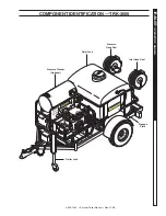
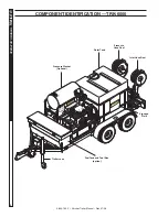
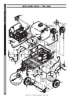
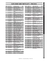
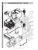
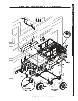
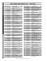
COMPONeNT iDeNTifiCaTiON 

Summary of Contents for TRK-3500

Page 1: ...25 White 40 OPera TiNg iNSTrU CTiON S iNSTrU CCiON eS De OPera CiON MODe D eMPlO i hOU r MeT er BUr Ner reS eT Off ON TeM Per aTU re CON TrO l O i aPagar qUeMaDO r BrUleU r hOrOMeT rO ChrONOM eTre CONTrOl De TeMeraT Ura CONTrOl e De TeMPera TUre PreNDer Off f 10 02033 200 165 130 95 235 270 300 MODEL ORDER MODEL TRK 3500 1 103 806 0 TRS 3500 TRK 6000 1 103 807 0 TRS 3600 ...

Page 2: ......

Page 3: ...future reference CONTENTS 9 800 199 0 Kärcher Trailer Manual Rev 01 08 Introduction 4 Machine Safety 4 Reporting Safety Defects 4 Checklist Before Your First Trip 4 What to Check How to Check 4 6 Component Identification TRK 3500 7 Component Identification TRK 6000 8 Brakes 9 Trailer Storage 9 Exploded View TRK 3500 10 Exploded View Parts List TRK 3500 11 Exploded View TRK 6000 12 13 Parts List TR...

Page 4: ...ation of the bolt holes Thank you for purchasing a Kärcher trailer This manual is designed to provide information for you to understand use and maintain Kärcher trailers TRK 3500 and TRK 6000 Owner User Responsibility The owner and or user must have an understanding of the manufacturer s operating instructions and warnings before using this equipment Warning information should be emphasized and un...

Page 5: ...the rated load If the load is not equal on all tires due to trailer weight distribution use the tire rated for the heaviest wheel position Note The capacity rating molded into the sidewall of the tire is not always the proper rating for the tire if used in a trailer application Use the following guideline 1 LT and ST tires use the capacity rating molded into the tire 2 Passenger Car Tires Use the ...

Page 6: ...ort distance about 1000 ft or until trailer does not grab or pull to one side anymore This action smooths down the brake bands Note Do not lock up the wheels Breakaway Switch Option D O T Wet Cell Battery After hitching to the tow vehicle pull the safety pin on the breakaway switch Check to see if system is operational Push safety pin back in to its original position Check battery fluid level ever...

Page 7: ... MODe D eMPl Oi hOU r MeT er BUr Ner reS eT Off ON TeM Per aTU re CON TrO l O i aPagar qUeMaD Or BrUl eUr hOrOMe TrO ChrONO MeTre CONTrO l De TeMera TUra CONTrO le De TeMPer aTUre PreNDe r Off f 10 02033 200 165 130 95 235 270 300 Pressure Washer Optional Water Tank Pressure Hose Reel Inlet Hose Reel Trailer Jack Signage Plate component identification TRK 3500 ...

Page 8: ... hOU r MeT er BUr Ner reS eT Off ON TeM Per aTU re CON TrO l O i aPagar qUeMaDO r BrUleU r hOrOMeT rO ChrONOM eTre CONTrOl De TeMeraT Ura CONTrOl e De TeMPera TUre PreNDer Off f 10 02033 200 165 130 95 235 270 300 Pressure Washer Optional Water Tank Pressure Hose Reel Inlet Hose Reel Trailer Jack Fuel Tank and Tool Box option Signage Plate component identification TRK 6000 ...

Page 9: ...oid creating or breathing dust 2 Avoid machining filing or grinding the brake lin ings 3 Do not use compressed air or dry brushing for clean ing Dust can be removed with a damp brush Trailer Storage Preparation If your trailer is to be stored for an extended period of time or over the winter it is important that the trailer be prepared properly 1 Remove the emergency breakaway battery and store in...

Page 10: ...5 8 22 20 23 23 35 60 55 22 21 4 3 4 51 22 47 Breakaway Unit Optional 10 41 22 60 55 22 23 23 35 1 20 45 22 21 23 23 54 20 25 24 19 18 38 23 28 23 35 17 22 30 16 14 16 21 23 58 9 29 36 61 37 39 40 59 Garden Hose Reel Optional 12 13 23 21 35 57 41 2 27 56 48 Hose Reel Optional 61 46 50 49 38 56 15 31 15 26 Hydrauylic or Electric Brakes Optional exploded view TRK 3500 ...

Page 11: ... Brass Float 1 26 8 707 342 0 Valve 1 1 2 Ball Polypropylene 1 27 8 711 640 0 Hose 3 8 x 125 2 Wire Swivel x Swivel 1 28 9 802 261 0 Hose 3 4 Push On 12 5 ft 29 8 706 928 0 Bushing 1 x 1 2 Black Poly 1 ITEM PART NO DESCRIPTION QTY 30 9 802 131 0 Elbow 1 2 JIC x 1 2 1 31 8 706 375 0 Elbow 1 1 2 FT x FT 1 32 8 706 925 0 Bushing 3 4 x 1 2 Pipe 1 33 8 706 829 0 Elbow 1 2 Street Brass 1 34 9 802 146 0 ...

Page 12: ... rOl O i aPagar qUeMaDOr BrUleUr hOrOMeTr O ChrONOMe Tre CONTrOl De TeMer aTUra CONTrOle De TeMPer aTUre PreNDer Off f 10 02033 200 165 130 95 235 270 300 24 64 7 10 6 11 5 4 27 10 2 13 57 34 55 35 7 9 63 10 33 10 63 61 9 8 10 9 7 10 27 12 62 26 50 61 57 53 51 Skid Mount Plumbing W O Garden Hose Option 8 9 9 32 31 30 37 36 52 28 29 35 Garden Hose Reel Optional Hose Reel Optional 14 62 33 10 10 exp...

Page 13: ...13 TRAILER OPERATOR S MANUAL 17 16 58 46 18 19 15 45 56 60 59 21 21 9 8 10 3 1 3 25 9 8 10 33 48 20 40 40 56 47 40 40 23 Hydraulic or Electric Brakes Optional Breakaway Optional 44 42 41 41 9 7 39 49 Reversed View exploded view Right side TRK 6000 ...

Page 14: ...150 2 Wire Swivel x Swivel 1 27 9 802 261 0 Hose 3 4 Push On 12 5 ft 28 8 706 928 0 Bushing 1 x 1 2 Black Poly 1 ITEM PART NO DESCRIPTION QTY 29 9 802 131 0 Elbow 1 2 JIC x 1 2 90 1 30 8 706 925 0 Bushing 3 4 x 1 2 Pipe 1 31 8 706 829 0 Elbow 1 2 Street Brass 1 32 9 802 146 0 Swivel 1 2 MP x 3 4 GHF W S 1 33 4 02120050 Hose 3 4 Suction Push On 15 33 ft 34 8 706 917 0 Bushing 1 2 x 3 8 Brass 1 35 8...

Page 15: ...9 800 199 0 Kärcher Trailer Manual Rev 01 08 15 TRAILER OPERATOR S MANUAL wiring diagram ...

Page 16: ...nd connections Every trip Breakaway Battery Pull switch pin check charge indicator light Every trip Load Distribution Check load distribution security Every trip Leveling Jacks Check fastenings Lube Every trip Welds Check all weld beads for cracks or separations Every 6000 mi or 6 mos Hinges Grease zerks with a Lithium complex grease Every 3000 mi or 3 mos Tie Down Devices Check for fracturing dis...

Page 17: ...ts Hose NOT Included 8 902 447 0 Kit For 100 of 3 8 High Pressure Hose All Models 8 902 448 0 Kit For 200 of 3 8 High Pressure Hose All Models 8 902 449 0 Kit For 100 of 3 4 Garden Hose All Models Chemical Rack 8 912 409 0 2 5 Gal Bucket Chemical Rack TRK 3500 TRK 6000 Fuel Tank Tool Box 8 902 464 0 Kit Fuel Tool 50 Gal Tank TRK 6000 8 902 465 0 Kit Fuel Tool 24 Gal Tank TRK 6000 8 707 521 0 Kit F...

Page 18: ...Hoses 8 711 798 0 50 x 3 4 8 711 799 0 75 x 3 4 8 711 800 0 100 x 3 4 Chrome Wheel Fender 8 902 466 0 Upgrade to Chrome Wheels per pair All Models 8 902 468 0 Upgrade to Chrome Fender Assy Tandem Axle per pair TRK 6000 8 902 467 0 Upgrade to Chrome Fender Assy Single Axle per pair TRK 3500 8 707 493 0 Chrome Wheel with ST205 75R14 C Tire each All Models Signage 8 902 469 0 Signage Plate All Models...

Page 19: ... not covered by this warranty Suspension axles torflex axles hubs drums brakes bearings and seals These are subject to the warranties if any of their manufacturers We shall not be liable for special indirect incidental or consequential damages of any kind including but not limited to labor costs or transportation charges in connection with the replacement or repair of defective parts Any implied o...

Page 20: ...Form 9 800 199 0 Revised 01 08 Printed in U S A ...

Reviews: