Operating Instructions English
Bild neu
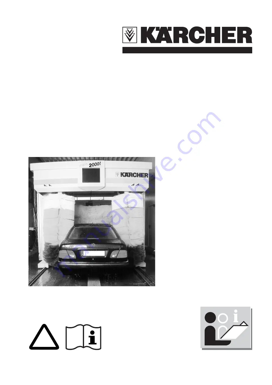
CWP 2000
1.267-071 CWP 2307
1.267-091 CWP 2309
1.267-371 CWP 2307 GOOD
1.267-391 CWP 2309 GOOD
1.267-471 CWP 2307 BEST
1.267-491 CWP 2309 BEST
1.267-517 CWP 2307 EF
1.267-691 CWP 2309 NP
5.959-373 A 2006471 (06/03)
!
www.karcher.com


