English
11
´
1
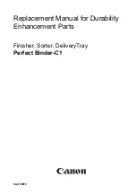
Spacer roller with holder
2
Washer
3
Screw
3. Unscrew the screw.
4. Position a sufficient number of washers between the
suction bar and spacer roller so that the suction lips
have the correct bend.
5. Fit the remaining washers above the spacer roller.
6. Screw in and tighten the screw.
7. Repeat the entire procedure at the other spacer roller.
8. Push the device a small distance forwards.
9. Check the bending of the suction lips over the entire
length.
10.If necessary, repeat the entire adjustment process.
Cleaning
Switching the device on
1. Turn the key-operated switch to "1".
The display shows the following one after the other:
Period of time until the next after-sales Customer Ser-
vice
Software version, control panel
Charging state of the battery and number of operating
hours
Driving
Note
The travel direction can be changed during the cleaning
operation. This way, a certain position can be intensively
cleaned by driving back and forth several times.
1. Set the travel direction switch to "forward".
Note
To reduce vehicle width, the suction bar can be fastened to
the transport holder. Narrow spaces can then be easily
passed through.
Cleaning
Note
The inclination and height of the suction bar can be adjust-
ed to improve the vacuuming results (see chapter
).
Note
When the waste water tank is full, the float switch closes
the suction opening and the suction turbine runs at a high-
er speed. In this case, raise the suction bar and drive to the
location for emptying the waste water tank.
1. Turn the working speed rotary knob to the desired value.
The speed is shown on the display during the adjust-
ment. The display is shown in percentage of the maxi-
mum speed.
2. Set the water volume at the regulating valve.
3. Press the suction bar lever downwards.
The suction bar lowers.
Suctioning begins.
4. Press the cleaning head lever downwards, unlatch it
and allow it to move upwards.
5. Pull the safety button towards the push handle.
The cleaning head starts up and the device moves at
the set speed.
Increasing the brush contact pressure
1. Let go of the safety button.
2. Lift the cleaning head lever up with your hand and en-
gage it towards the right.
Finishing operation
Finishing cleaning
1. Let go of the safety button.
2. Press the cleaning head lever downwards and engage
it towards the right.
3. Continue moving a short distance.
The residual water is vacuumed up.
4. Lift the suction bar.
The suctioning continues to run for 10 seconds after-
wards.
5. Turn the key-operated switch to "0".
6. Charge the batteries if necessary.
Draining the waste water
몇
WARNING
Improper disposal of waste water
Environmental pollution
Observe the local waste water treatment regulations.
1. Remove the drain hose from the support and lower it
over a suitable collecting device.
2. Press the dosing device together or kink the hose.
3. Open the dosing device cover.
4. Drain the waste water. Regulate the water volume by
pressing or kinking.
5. Rinse the waste water tank with clear water.
Draining fresh water
1. Pull off the filling level display hose and swivel it down.
Draining fresh water quickly
1. Unscrew the fresh water tank lock.
2. Allow the fresh water to drain away.
10 mm
1 2
3
Summary of Contents for BD 80/100 W Classic Bp
Page 2: ......