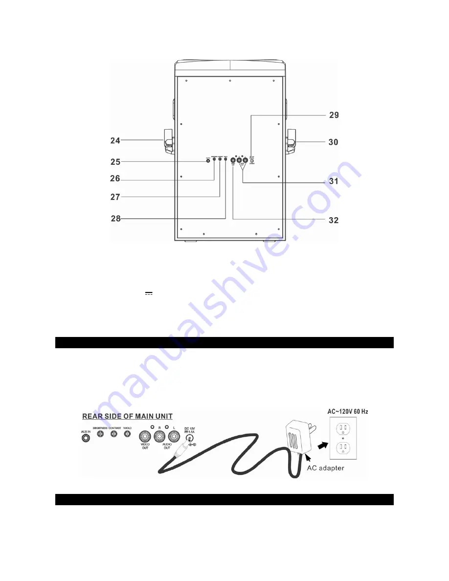
Karaoke Night KN355 User Manual Download Page 6


REAR PANEL 


24. 

MICROPHONE HOLDER (RIGHT SIDE) 

25. 

AUX-IN JACK (3.5mm) 

26. 

BRIGHTNESS CONTROL KNOB    (To adjust monitor brightness) 

27. 

CONTRAST CONTROL KNOB    (To adjust monitor contrast) 

28. 

V-HOLD CONTROL KNOB    (To adjust picture scrolling) 

29. 

DC JACK DC12V


30. 

MICROPHONE HOLDER (LEFT SIDE) 

31. 

AUDIO OUTPUT JACKS (WHITE CODED FOR LEFT, RED CODED FOR RIGHT) 

32. 

VIDEO OUTPUT JACK (YELLOW CODED) 


POWER SOURCES 

AC OPERATION 

Plug the supplied AC adapter into the DC jack (12V DC input ) on the rear panel of the unit and connect to a 
standard AC wall socket. Press the POWER ON/OFF button on the Karaoke system to turn on and the 
POWER INDICATOR will light. 

Note:

 When the unit is not operated for long periods of time, unplug the AC adapter from the unit and wall 

outlet. 


CONNECTING TO AN EXTERNAL TV/MONITOR 

The karaoke system provides a patch cord to give you the option of connecting your unit to an external 
audio/video device. The patch cord has three RCA plugs at each end. White and Red are for left and right audio 

Summary of Contents for KN355

Page 1: ...L For further information on this model and the entire lineup of Karaoke Night products please visit www karaokenightusa com PLEASE READ THIS USER MANUAL COMPLETELY BEFORE OPERATING THIS UNIT AND RETA...

Page 2: ...where it is warm and damp water droplets or condensation may form inside the CD player When there is condensation inside the unit the unit may not function normally If condensation occurs let unit sta...

Page 3: ...ctronics Group want you to get the most out of your equipment by playing it at a safe level One that lets the sound come through loud and clear without annoying blaring or distortion and most importan...

Page 4: ...operations Next go to the section for the specific operation you wish to perform For your easy reference listed here are some of the main features of this Karaoke System Monitor allows you to see the...

Page 5: ...TON 7 ECHO KNOB 8 AVC KNOB 9 BALANCE KNOB 10 CD DOOR LATCH 11 BUILT IN B W MONITOR 12 PLAY PAUSE BUTTON 13 STOP BUTTON 14 PROGRAM BUTTON 15 DIGITAL KEY CONTROLS 16 MASTER VOLUME CONTROL 17 MIC 1 MIC 2...

Page 6: ...ION Plug the supplied AC adapter into the DC jack 12V DC input on the rear panel of the unit and connect to a standard AC wall socket Press the POWER ON OFF button on the Karaoke system to turn on and...

Page 7: ...n the supplied patch cord Plug the white end of the patch cord into the white AUDIO OUT jack on the unit Plug the red end of the patch cord into the red AUDIO OUT jack on the unit Now connect the othe...

Page 8: ...e Microphone The Microphone sensitivity and loudness can be adjusted as required by turning the corresponding MIC VOLUME control and or MASTER VOLUME control 5 Turn off the unit after use by pressing...

Page 9: ...cable to an external TV monitor or home stereo system instead TV and or home stereo system are not included STOP MODE If the STOP button is pressed in the course of playing the disc will cease to pla...

Page 10: ...roller to shut down automatically If this occurs simply disconnect the AC Adapter Wait for at least 3 minutes and then setup the unit again as if you were using it for the very first time CARE AND MAI...

Page 11: ...TV VIDEO IN jacks No song lyrics appear on the Built in Monitor or External TV screen MONITOR is off Turn on the built in monitor with the MONITOR ON OFF button Source selector on TV is not set to VID...

Page 12: ...t in compliance with electrical codes or SPECTRA user manual specifications or failure to provide reasonable care and necessary maintenance as outlined in the user manual 3 Warranty of all SPECTRA pro...

Reviews: