background image

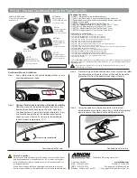
Step 6: Removing Projector from Ceiling

The Projector Adapter 

(V)

 is designed to be easily 

removed from the ceiling plate or extension tube for 
cleaning, servicing, realignment and tensioning, as 
shown in Diagram H.

Remove the two Safety Screws (

O

) holding the 

Projector Adapter to the ceiling plate or extension 
tube.

Gently push up on the Projector / Projector Adapter to 
disengage the Spring Loaded Locking Tabs.

Turn the projector slightly left or right so the locking 
tabs cannot re-engage into the ceiling plate or 
extension tube, and pull the projector down to 
remove.

WARNING 

Support the weight of the projector so it does not fall from your mount.

6

O

O

Diagram H

6.1

6.2

6.4

6.5

6.6

6.3

Spring Loaded 

Locking Tabs

Step 5: Tilt the Projector

The P101/P101W tilts up to 20

°

 in any direction, by way of a ball joint inside the Projector Adapter (

V

). Once 

the projector is mounted to the ceiling plate, you can adjust the tilt by holding the projector and pushing it in 
the direction you need. The tension should be firm, so that the projector will remain in the position you desire 
when you stop applying pressure.

NOTE: The Projector Adapter (

V

) has a tensioning ring that comes pre-tensioned from the factory. If the ball 

joint is too tight to move with reasonable pressure, or too loose to stay in position, you will need to adjust 
the tension. Should you find your installation requires this ring to be adjusted and re-tensioned, remove the 
projector from the ceiling as described in Step 6, and follow the tensioning procedure as described in the 
optional Step 7.

Step 4: Attach Projector to Ceiling

The P101/P101W has two spring loaded locking tabs that 
allow easy installation to the ceiling plate assembly.

Push the Projector Adapter 

(V) 

up into the ceiling plate 

or extension tube. The 2 spring loaded locking tabs 
will catch in 2 of the 4 square holes in the ceiling plate 
or extension tube. Take caution to ensure the Projector 
Adapter 

(V) 

engages; see Diagram G.

Once you have the Projector Adapter locked into the 
ceiling plate or extension tube, install the 2 Safety Screws 
(

O

).

The projector can now be gently twisted left or right, or 
/- 20° to aim at your screen.

Diagram G

O

O

V

Spring Loaded 

Locking Tabs

4.1

4.2

Summary of Contents for P101

Page 1: ...User Manual P101 P101W Projector Ceiling Mount Supporting your digital lifestyle TILTING EXTENDABLE PROJECTOR CEILING MOUNT English 22 lb 10 kg 3 12 7 5 30cm 360 20 ...

Page 2: ... or support kantoliving com Kanto can not be liable for property damage or injury caused by incorrect mounting incorrect assembly lifting or incorrect use of this product CAUTION The maximum loading weight is 22 lbs 10 kg This projector mount is intended for use up to the maximum weight restrictions indicated Use with products heavier than the maximum weights indicated may result in instability ca...

Page 3: ...g Plate V Projector Adapter W Outer Extension Tube X Inner Extension Tube Y Extension Brackets 75mm 150mm Z Wrench x2 M2 5 x 15mm with washers M3 x 15mm with washers M3 x 20mm with washers M4 x 15mm M4 x 20mm M4 x 25mm M5 x 15mm M5 x 20mm M5 x 25mm M6 x 15mm M6 x 20mm M6 x 25mm x4 each A B C D E F G H I J K L Bolts 1mm thick 2mm thick 4mm thick Base Spacers x4 Crescent Wrench Phillips Screwdriver ...

Page 4: ...acing one by one as required The flexibility of the mount and the varying arm lengths will mean there is more than one solution for fitting the arms to your projector It is best to use the shortest arm configuration possible while maintaining a suitable center of gravity for the projector See Diagram C Once the appropriate arm configuration has been selected and assembled the projector adapter sho...

Page 5: ...e Optional Extension Tubes If you need your projector suspended 9 to 12 from the ceiling attach the two extension tubes included in the P101 P101W box referring to Diagram E Step 3 1 Assemble Outer Extension Tube W to Inner Extension Tube X at the desired length using an M8 x 55mm bolt N and locking nut N as shown in Diagram E Step 3 2 Use two Set Screws P to ensure the rods are held firmly togeth...

Page 6: ... be firm so that the projector will remain in the position you desire when you stop applying pressure NOTE The Projector Adapter V has a tensioning ring that comes pre tensioned from the factory If the ball joint is too tight to move with reasonable pressure or too loose to stay in position you will need to adjust the tension Should you find your installation requires this ring to be adjusted and ...

Page 7: ...e desired level of tension Use the Wrench Z if necessary Step 7 3 Tighten the locking nut with Wrench Z to ensure the Plastic Tension Ring cannot loosen 7 1 7 2 7 3 Diagram I Z Plastic Tension Ring Locking Nut The Projector Adapter V Tensioning Ring comes pre tensioned from the factory Should you find your installation requires this ring to be adjusted and re tensioned follow this procedure referr...

Page 8: ...e repaired at the current price of parts and labor in effect at the repair Such repairs are warranted for 90 days from the day of reshipment to the original purchaser This warranty is in lieu of all other warranties expressed or implied including without limitation any implied warranty or merchantability or fitness for any particular purpose all of which are expressly disclaimed Customers will be ...

Reviews: