background image

7

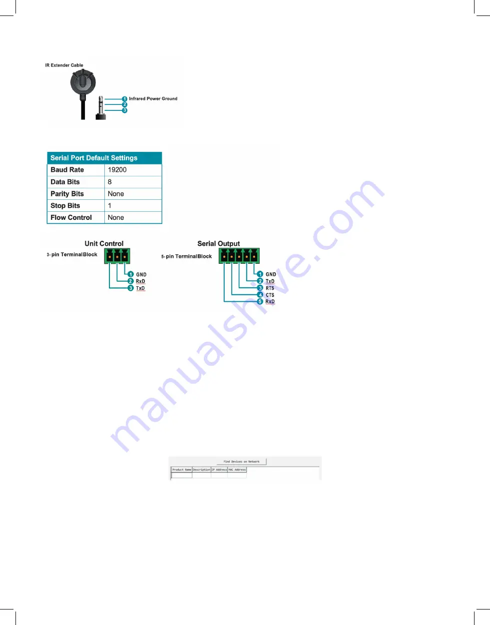
  6.4 IR Cable Pinouts

  6.5 RS-232 Pinout and Defaults


  6.6 WebGUI Control

•  Device Discovery

Please obtain the “Device Discovery” software from your authorized dealer and save it in 
a directory where you can easily find it.
Connect the unit and your PC/Laptop to the same active network and execute the 
“Device Discovery” software. Click on “Find Devices on Network” and a list of devices 
connected to the local network will show up indicating their current IP address.

Note: This unit defaults to DHCP mode. The current IP address can be verified using the HDMI 
output or RS-232 if the Device Discovery software is not available.

By clicking on one of the listed devices you will be presented with the network details of 
that particular device.

Summary of Contents for EXT-PROCTRL

Page 1: ...VER 1 0 All Right Reserved MPN EXT PROCTRL Flexible Matrix System Controller powered by SDVoE w POE RS 232...

Page 2: ...product Never push an object of any kind into this product through any openings or empty slots in the unit as you may damage parts inside the unit Do not attach the power supply cabling to building su...

Page 3: ...Pinout and Defaults 5 6 6 WebGUIControl 6 6 6 1 Monitor Control Tab 8 6 6 2 System Tab 21 6 6 3 Settings Tab 24 6 6 4 Transmitter Tab 35 6 6 5 Receiver Tab 39 6 6 6 Scaling Tab 43 6 6 7 Video Wall Tab...

Page 4: ...r pair could only be configured in a basic point to point operational mode Additionally this unit supports controlling and configuring the matrix video wall and multiviewer modes of connected SDVoE un...

Page 5: ...ndard Optional Trigger Control Keypad support for easy single button macro activation Optional Standard control is available via WebGUI remote or local RS 232 Telnet and IR Remote 6 OPERATION CONTROLS...

Page 6: ...ch to your PC laptop to control the unit via WebGUI Telnet 8 LAN 1 POE Port This port is used to connect to the SDVoE devices to be controlled Connect to the SDVoE units private network through their...

Page 7: ...active network and execute the Device Discovery software Click on Find Devices on Network and a list of devices connected to the local network will show up indicating their current IP address Note Th...

Page 8: ...load and display the System tab Click Login to open the authentication window Please enter the appropriate user name and password then click Enter to log in If a keyboard is not available such as when...

Page 9: ...are not currently detected will still be displayed however they will have a disconnected icon and cannot be used for routing 1 Video Routing Provides drag and drop control over the video routing betw...

Page 10: ...rom a source To do this first select the type of stream to stop by clicking on the cycle selection icon at the bottom of the window until the preferred option All Stop Native Stop Multiview Stop is di...

Page 11: ...1 Video Wall Routing Provides drag and drop source selection for pre defined video wall groups Note Video wall groups are defined within the Video Wall tab please see section 6 6 7 for more informati...

Page 12: ...ce If one or more of the displays in the group is not currently active those windows will be blue 2 Multiview Selection Provides drag and drop output selection and window source selection for pre defi...

Page 13: ...rted when the receiver s HDMI audio device setting is set to HDMI Audio Follow Video in Genlock Mode HDMI Audio Transmitter This section provides drag and drop buttons for all transmitters detected by...

Page 14: ...topped by using this control HDMI Audio Receiver This section provides drag and drop buttons for all receivers detected by the system as well as a button target to stop one or all independent HDMI aud...

Page 15: ...ly routed receivers Note Receivers may also be drag and dropped onto sources to activate a new route Source to Multiple Receiver Routing To route an analog audio source to multiple receivers at the sa...

Page 16: ...transmitters and receivers Note When a USB host port has enabled Simultaneous Mode it can be paired with up to 7 device endpoints If Simultaneous Mode is disabled a USB host port can only be paired wi...

Page 17: ...put needs to be sent to more than one output the Global Broadcast option must be used IR Input This section provides drag and drop buttons for all IR input ports detected by the system as well as a bu...

Page 18: ...iple RS 232 senders however each RS 232 sender may only be directly routed to a single RS 232 receiver If an RS 232 sender needs to be sent to more than one receiver the Global Broadcast option must b...

Page 19: ...appear below the RS 232 sender s name within its button Clicking on any RS 232 receiver button will change the color of itself and all RS 232 senders currently routed to it Note RS 232 senders may al...

Page 20: ...nformation as appropriate for the connected network Press Save to activate the changes Note Both LAN ports default to DHCP mode The current IP address can be verified using the HDMI output or RS 232 i...

Page 21: ...e several minutes to complete especially if there are a large number of transmitters and receivers in the system Please do not power off any units during the update process IP Master Controller Firmwa...

Page 22: ...lete them To add a new group click on the Add icon and then select the preferred options and endpoints To edit an existing group click on the Edit icon and then make whatever changes are required Once...

Page 23: ...tool They can be as simple as selecting a new input for a receiver or a complex sequence of source resolution mode and audio changes executed in sequence Up to 16 macros can be defined and each macro...

Page 24: ...ting command click on the Delete icon next to the appropriate command Note Clicking on Confirm or Add only stores the current changes to the command list of the macro currently being edited The entire...

Page 25: ...then click Send to transmit the command immediately Note To transmit hex data each ASCII hex pair octet must be preceded by x For example a carriage return would be x0D 4 I O Trigger This section pro...

Page 26: ...source adapts to the new information Load EDID To update the EDID of one or more transmitters with a previously saved User EDID click the Load EDID button to open the file selection window and then se...

Page 27: ...cute button in the bottom right window to finalize the assignment Receiver EDID Lists all available receivers To copy the EDID from the display attached to one of these receivers to one or more transm...

Page 28: ...ime the unit has been online since the last reboot Daylight Enable or disable support for daylight savings time 7 Schedule This section provides access to the settings and controls for configuring sch...

Page 29: ...selected macro a single time on a specified day After the configuration is complete click on the Save Schedule button at the bottom of the page to store the schedule event Activate Date Clicking on t...

Page 30: ...Times Enter the number of times the schedule event should repeat Entering 0 will make the event continually repeat Weekly Select Weekly to execute the selected macro at a specific time on set days of...

Page 31: ...ver they will have a disconnected icon and cannot be used for routing These units may be removed from the list using the Remove button 1 Transmitter Configuration Remove Click on this button to remove...

Page 32: ...including IP mode and allow for those settings to be changed To activate any changes made please click on the Save button to close the window RS 232 Settings Clicking this button will display a pop u...

Page 33: ...upport Enable or disable support for HDCP 2 2 sources Bypass Divide FPS by two Enable or disable the Divide FPS Frames Per Second by Two feature on the primary video stream generated by this unit Enab...

Page 34: ...e pop up window provides a dropdown to select the unit to be removed Once the selection has been made click on Confirm to apply the change Note Only disconnected receivers can be removed Hello Clickin...

Page 35: ...ud rate and allow for those settings to be changed To activate any changes made please click on the Save button to close the window Device Settings Provides controls over a number of unit specific fun...

Page 36: ...ources with LPCM audio HDMI Audio All Channel Output the HDMI audio routed to this unit Note This mode only supports HDMI sources with LPCM audio Analog Audio Source Select the audio source type to ou...

Page 37: ...te Due to this scaling occurring only on the receiver side changes to resolutions here has no impact on bandwidth usage 1 Resolution Selection To select an output resolution for a receiver click and d...

Page 38: ...wall group click on the Execute button To delete an existing video wall group click on the Delete icon next to the appropriate group s name Note Deleting a video wall preset will not disable the video...

Page 39: ...ed and is in video wall mode red panels indicate that a display has been assigned but is not active in the correct mode and blue panels indicate that no display has been assigned yet Save Group Click...

Page 40: ...bed if it is currently active To completely remove a multiview output a new source needs to be routed to the display or the output needs to be disabled from the Monitor Control Tab Order Use the dropd...

Page 41: ...e and a blue panel indicates that no source has been assigned yet Save Preset Click this button to save changes to the current multiview configuration without activating it Execute Click this button t...

Page 42: ...42 6 8 RS 232 and Telnet Commands...

Page 43: ...43...

Page 44: ...44...

Page 45: ...45...

Page 46: ...46...

Page 47: ...47...

Page 48: ...48...

Page 49: ...49...

Page 50: ...50...

Page 51: ...51 Note Commands will not be executed unless followed by a carriage return Commands are not case sensitive...

Page 52: ...PROCTRL Sources Displays Projector Decoder Mode LAN Cable Extend up to 120 meters 495 feet over CAT6a 10G POE NETWORK SWITCH EXT PROCTRL Multi Viewer TV Wall x1 RX in this case for each screen x9 RX...

Page 53: ...SB 2 0 Type A IR Frequency 38kHz Baud Rate 19200 Power Supply 5V 2 6A DC US EU standards CE FCC UL certified ESD Protection HBM 8kV Air Discharge 4kV Contact Discharge Dimensions WxHxD 231 5mmx25mmx10...

Page 54: ...54 8 2 Video Specifications...

Page 55: ...lor Data rates lower than 5 3Gbps or below 225MHz TMDS clock 4K30 4K UHD Video 4K 24 25 30Hz 4K 50 60Hz 4 2 0 8 bit color Data rates higher than 5 3Gbps or above 225MHz TMDS clock but below 10 2Gbps 4...

Page 56: ...56 9 ACRONYMS...

Page 57: ...ting our specifications No certificate or invoice as the proof of warranty The product model showed on the warranty card does not match with the model of the product for repairing or had been altered...

Reviews: