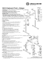
18810 Table-Style
Keyboard Stand »Omega«
- An appealingly designed practical and very stable keyboard stand
- Load capacity: 80 kg
- Four point support with protective rubber discs
- Support arms width: 180, 300, 420, 550, 670, 790 mm, depth: 345 mm
- Adjustable height from 600 - 1020 mm in 29 stages,
-
comfortable and quick with engage and lock knobs
- Weight: 9.5 kg
- Optional add-ons: 18811 and 18822 Stacker (2. level resp. 3. level),
-
18819 and 18824 Controller keyboard tray (for 18811 resp. 18822),
-
18827 Digitalpiano-Auflage, 18814 Adapter, 18807 and 18817 Universal holder,
-
18805 Sheet music and concept holder, 18815 Laptop holder, 18806 Trolley
Thank you for choosing this product. Please read and follow these instructions carefully before
setting up and operating this product. It informs you about all important steps to ensure safe
handling. We recommend that you keep them for future reference.
KÖNIG & MEYER
GmbH & Co. KG
Kiesweg 2, 97877 Wertheim, www.k-m.de
18810-015-55/76/91 Rev.11/08/09 03-80-254-00 05/22
SAFETY INSTRUCTIONS
GENERAL
- The possibility to adjust the product involves entrapment hazards. Therefore careful
-
and thoughtful handling during installation, operation, dismantling and maintenance
-
is essential.
- Protect the stand from adverse external conditions (moisture, wind, shocks).
- The careful and diligent treatment preserves the functionality,
-
durability and ensures last not least safety.
- Faulty products are not to be used; damaged parts must be replaced or repaired
-
before handling
OPERATION
- Maximum load 80 kg (including additions)
- Ensure that the subsurfaces are stable and even
- The locking bolt of both clamping screws must always be engaged
- Always remove the keyboards before you adjust the height
- The maximum height is reached as soon as the STOP mark on the stand tube
-
becomes visible (see chapter HEIGHT ADJUSTMENT)
- both tubes must always be adjusted to the same height
- The long side of the supports must point in the direction of the long base sides
- Screw connections must be firmly tightened
SET-UP INSTRUCTIONS
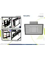
1. COMPONENTS
Please carry out a visual inspection to ensure that all parts are complete and in good as
order far as can be seen.
a
base frame (2x),
b
U-bracket,
c
support arm (2x)
Accessories bag:
d
rubber pads ø 20 mm (4x),
e
cable clamp (4x),
f
carriage bolt M6 x 65 mm (2x),
g
washer ø 6,4 mm (2x),
h
wing nut M6 (2x),
i
spring-loaded clamping knob (2x)
2. ASSEMBLY and HANDLING
STAND
2.1
Insert one of the base frames
a
into the U-bracket
b
...
2.2
...and fix by using spring-loaded clamping knob
i
- for this purpose:
2.2.a
Screw the spring-loaded clamping knob approx. 5 turns into the threaded bushing...
2.2.b
...and now move the base frame a slightly until the front bolt of the spring-loaded
2.2.b
clamping knob audibly engages in a hole.
2.2.c
Finally, fully tighten the spring-loaded clamping knob
i
.
NOTE:
Mount the second base frame
a
in the same way. Please ensure that the height setting is
the same (see also the scale on the base frame).
SUPPORT ARMS c
2.3
We recommend symmetrical mounting of the two support arms (z-z...u-u).
2.4
The long side of the support points in the direction of the holes on the base frame
a
.
2.5
Insert carriage bolt
f
through the support arms
c
and the desired borehole of
2.7
the u-bracket and screw together with washer
g
and wing nut
h
.
RUBBER PADS d
2.6
They are self-adhesive and can when needed be placed
c
on the desired position of
2.6
the support - e.g. when the instrument touches down between the two large rubber
2.6
protectors because the depth is too small.
CABLE CLAMPS e
2.7
They keep the wiring in order.
2.7
They can be positioned anywhere on the U-bracket
b
.
2.8
Procedure: Position the opening of the clamp slightly diagonally on the tube,
2.8
press until both brackets open, enclose the tube and audibly snap-in.
2.9
The cable clamps can be moved on the U-bracket.
ADJUSTMENT PLATE for FLOOR LEVELING
2.10
To compensate for uneven floors, the two front parquet protectors have adjustment
2.10
plates (ribbed surface), which can be turned out up to approx. 7 mm if necessary.
1. COMPONENTS
2. ASSEMBLY and HANDLING
6-18810-30-00

