background image

WZA

School ventilation

Assembly, installation and operating instructions

31

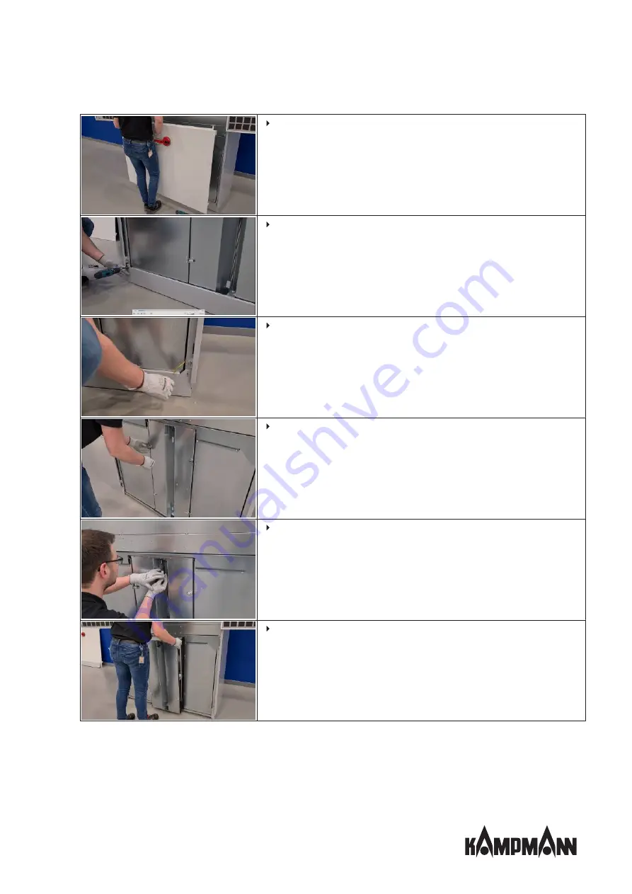
Carefully lift the service panel and remove it.

Remove the 2 self-locking screws M8x12 from the plinth.

Remove the earthing cable from the plinth and remove the plinth.

Loosen the 4 snap-in connections.

Loosen the locking latch at the top and bottom.

Pull the air duct element forwards and remove it.

Summary of Contents for WZA

Page 1: ...WZA Assembly installation and operating instructions Keep these instructions in a safe place for future use Issue03 22EN SAP No 1541809...

Page 2: ......

Page 3: ...ery 10 3 3 Storage 11 3 4 Packaging 11 4 Technical data 12 5 Construction and function 13 5 1 Overview 13 5 2 Brief description 13 5 3 Wear parts list 14 6 Installation and wiring 15 6 1 Connection op...

Page 4: ...nnection 28 11 2 Maintenance Schedule 28 11 3 Maintenance work 29 11 3 1 Replacing the filter 29 11 3 2 Cleaning the enthalpic heat exchanger 30 11 3 3 Clean the inside of the unit 32 12Faults 34 12 1...

Page 5: ...ontained in this manual In addition all local occupational health and safety at work regulations apply as do general safety provisions governing the use of the equipment Illustrations in this guide ar...

Page 6: ...ANT NOTE Do not damage the unit by heavy loads Avoid heavy loads this is not a seat as this may damage the casing and can impair the operation of the unit DANGER Avoid electric shocks and or fire haza...

Page 7: ...ver operate the unit in humid areas such as swimming pools wet areas etc Never operate the unit in rooms with an explosive atmosphere Never operate the unit in aggressive or corrosive atmospheres e g...

Page 8: ...ent this in the form of operating instructions for the operation of the unit The operator must regulate and specify the responsibilities for installation operation troubleshooting maintenance and clea...

Page 9: ...prevention regulations Guidelines and recognised technical regulations i e Association of German Electricians VDE regulations DIN and EN standards VDI 6022 maintenance personnel must be trained to Ca...

Page 10: ...applicable period for complaints More information is avail able in the T Cs on the Kampmann website IMPORTANT NOTE Material damage caused by incorrect transport Units being transported can drop or top...

Page 11: ...expose to aggressive media Protect from direct sunlight Avoid mechanical vibrations and shocks IMPORTANT NOTE Under certain circumstances packages can carry storage instructions that exceed the requi...

Page 12: ...evel 4 39 35 29 22 Sound power level 51 47 41 34 Tab 2 Technical data WZA Components Weight kg Functional unit 136 Enthalpic unit 136 Casing 110 1 according to EN 308 2 At outside air temperature 5 C...

Page 13: ...on unit for acoustically sensitive rooms such as classrooms and seminar rooms Other ap plications include nursery schools conference meeting rooms and similar types of room WZA ventilates according to...

Page 14: ...stallation and operating instructions 14 5 3 Wear parts list Figure Article Properties For use with Art no ISO Coarse replacement filter 1 set 1 no All WZA 683001020010 ISO replacement filter ePM1 55...

Page 15: ...s as shown in the figures below The connec tion versions are defined by the position of the outside air and exhaust air connection Connection on left side Connection on right side Connection at top le...

Page 16: ...conditions are met Make sure that the floor is sufficiently load bearing to withstand the weight of the unit Ensure that the unit is standing securely Ensure that the airflow can circulate freely 6 3...

Page 17: ...n top of the other Keep hands away from the contact surfaces and use suitable lifting equipment when lowering the en thalpic unit onto the functional unit Perform all steps to install and set up the u...

Page 18: ...lpic unit Remove any lifting tool used Use 4 self locking screws M8x12 to connect the functional unit and en thalpic unit to the corner profiles Use 4 earthing cables L 300 mm to connect the functiona...

Page 19: ...inth panel left 4 Plinth panel right 5 Front plinth panel 6R Room side lower casing panel 7R Window side lower casing panel 8R Room side upper casing panel 9R Window side upper casing panel 10 Upper f...

Page 20: ...xample unit right version 16 13 15R 14R 13 Lower service panel 14R Right service door 15R Left service door 16 Control unit Use 2 self locking screws M5x10 to attach casing element 13 to the front of...

Page 21: ...ventilation Assembly installation and operating instructions 21 Installing the control unit 16 Use 4 countersunk screws M4x10 to screw the control unit 16 in place Caution The Kampmann logo must poin...

Page 22: ...have been completed before installation of the unit Connect on site pipe connections 3 to exhaust air spigots 1 and outside air spigots 2 Fit the fa ade outlet optional accessory Fasten the wall fixi...

Page 23: ...d on the top of the unit Depending on the position of the unit in the room the dis charged supply air flow can be aligned or fanned out using 4 poppet valves Slightly loosen the 4 self locking screws...

Page 24: ...WZA with electric supplementary heating coil 1312 W 7 2 Power supply The electrical connection area of the WZA is located on the top of the unit beside the supply air outlet The unit is supplied ex w...

Page 25: ...been removed Electrical tests Check whether all lines have been properly laid Check whether all lines have the necessary cross section Are all wires connected in accordance with the electric wiring di...

Page 26: ...WZA School ventilation Assembly installation and operating instructions 26 9 Commissioning Insert the connection cable supplied into the mains socket then into the power socket...

Page 27: ...ntilation after 10 minutes Press the Solo key The unit switches to Stage 2 mode and changes back to Automatic ventilation after 8 h Press the Solo key The unit switches to Stage 1 mode and changes bac...

Page 28: ...prevent accidental restart 1 De energise the units by disconnecting the mains power plug 2 Prevent accidental re connection 3 Check that the equipment is de energised 4 Cover and cordon off adjacent...

Page 29: ...have sharp edges Wear suitable protective gloves Perform all the steps to simply change the filter as shown in the video 2 1 Check the outside air filter Use the locking lever to open the service fla...

Page 30: ...extract air filter from the filter flap and clean it or replace it if seriously dirty 11 3 2 Cleaning the enthalpic heat exchanger Perform all the steps to clean the enthalpic exchanger as shown in t...

Page 31: ...lift the service panel and remove it Remove the 2 self locking screws M8x12 from the plinth Remove the earthing cable from the plinth and remove the plinth Loosen the 4 snap in connections Loosen the...

Page 32: ...act with air internal surfaces of the unit outlet elements etc for dirt or deposits dur ing maintenance and use a commercially available product to remove Before cleaning it first remove the enthalpic...

Page 33: ...rawer forwards and clean the impeller Clean all surfaces of the functional unit that come into contact with air Once you have completed all cleaning work start to reassemble all parts in reverse order...

Page 34: ...fault requires work in the hazard area Immedi ately advise a supervisor on site about the fault 4 Either rectify the fault yourself or have it repaired by authorised personnel depending on the nature...

Page 35: ...rtyku u Typ Model slo v robku auf das sich diese Erkl rung bezieht mit der den folgenden Norm en oder normativen Dokumenten bereinstimmt to which this declaration relates is in conformity with the fol...

Page 36: ...ic 2014 30 EU EMV Richtlinie 2014 35 EU Niederspannungsrichtlinie Frank Bolkenius Lingen Ems den 10 08 2021 ___________________________________ Ort und Datum der Ausstellung Name und Unterschrift des...

Page 37: ...tteln 1 2 Einhaltung der Forderungen hinsichtlich verwendeter Materialien des Au enluftdurchlasses 2 1 Einhaltung der Forderungen hinsichtlich verwendeter Materialien dezentraler RLT Ger te 4 1 Einhal...

Page 38: ......

Page 39: ......

Page 40: ...KG Friedrich Ebert Str 128 130 49811 Lingen Ems T 49 591 7108 660 F 49 591 7108 173 E export kampmann de W Kampmann eu Country Contact Great Britain Kampmann UK Ltd Dial House Govett Avenue Shepperto...

Reviews: