background image

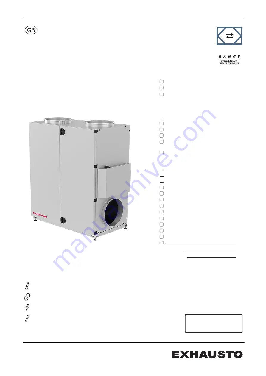
VEX160CF Vertical HCW

with EXact2 control

VEX100 CF

Product information........................................ Chapter 1 + 6

Mechanical assembly..................................... Chapter 2 + 3

Electrical installation.......................................Chapter 4

Maintenance...................................................Chapter 5

Unit supplied with (factory fitted):

The following accessories are supplied

separately:

VDI 6022
M5-compact filter, FP
F7-compact filter, FP

pieces, control panel, HMI
Motor valve, MVM ______K

vs

-value

Closing damper, LS500-24, (LSA exhaust)
Closing damper, LS500-24, (LSF outdoor)
Closing damper, LSR500-24, with 

spring-return (LSAR exhaust)
Closing damper, LSR500-24, with

spring-return (LSFR outdoor)
pieces, Fire thermostat, BT40
pieces, Fire thermostat, BT50
pieces, Fire thermostat, BT70
pieces, Constant pressure control, MPT-DUCT
Motion sensor, MIO-PIR
Humidity sensor, MIO-RH
CO

2

-sensor, MIO-CO2-DUCT

CO

2

-sensor, MIO-CO2-ROOM

Temperature sensor, MIO-TS-DUCT
Temperature sensor, MIO-TS-ROOM
Control for external cooling unit, MXCU
Mounting base, MSV160V
TS-RPT-X

Prod.order no.:
Sales order no.:

Original instructions

3005706-2017-06-08

VEX160CF V_HCW

EXHAUSTO A/S

Odensevej 76
GB-5550 Langeskov

Tel. +45 65 66 12 34
Fax +45 65 66 11 10
[email protected]
www.exhausto.dk

Summary of Contents for VEX100CF Series

Page 1: ...SR500 24 with spring return LSAR exhaust Closing damper LSR500 24 with spring return LSFR outdoor pieces Fire thermostat BT40 pieces Fire thermostat BT50 pieces Fire thermostat BT70 pieces Constant pressure control MPT DUCT Motion sensor MIO PIR Humidity sensor MIO RH CO2 sensor MIO CO2 DUCT CO2 sensor MIO CO2 ROOM Temperature sensor MIO TS DUCT Temperature sensor MIO TS ROOM Control for external ...

Page 2: ... 17 3 1 2 Installation on mounting base 17 3 2 Condensation outlet 17 3 2 1 Establishment of condensation outlet 17 3 3 Water heating coil 18 3 3 1 Principles for connecting the water heating coil 18 3 3 2 MVM valve 20 4 Electrical installation 4 1 Electrical installation 22 5 Maintenance hygiene and servicing 5 1 Operating readings via the HMI panel 23 5 2 Maintenance 23 5 2 1 Overview of mainten...

Page 3: ...6 3 Water heating system 30 6 3 1 MVM motor valve 30 6 4 Capacity diagram 31 6 5 Ordering spare parts 31 6 6 Environmental declaration 32 3005706 2017 06 08 3 36 ...

Page 4: ...rrect operation EXHAUSTO A S accepts no liabil ity for accidents caused by equipment not used in accordance with the manual s instructions and recommendations Supply air extract air This instruction manual uses the following terminology Supply air air blown in Extract air air removed Outdoor air Exhaust air Front page Acces sories The front page of the instruction manual contains a checklist detai...

Page 5: ...o the spigots with a maximum mesh size of 20 mm Lock the air han dling unit during operation The VEX unit must always be locked during operation Use the cylinder lock in the han dle Remember to remove the key from the lock Or use a padlock Use the han dle s built in padlock fixture Lock Padlock fitting Information plate The VEX unit rating plate shows VEX unit type 1 production number 2 1 2 NB Alw...

Page 6: ...r air Standard LS A LS A R Closing damper exhaust air Accessories BP1 Bypass damper Standard M1 Extract air motor Standard M2 Supply air motor Standard MC1 Motor controller motor 1 Standard MC2 Motor controller motor 2 Standard TE11 Temperature sensor extract air Standard TE12 Temperature sensor exhaust air Standard TE21 Temperature sensor outdoor air Standard TE22 Temperature sensor supply air St...

Page 7: ...nit is not to be used to transport solid particles or in areas where there is a risk of explosive gases 1 3 Location requirements Positioning The unit is designed for indoor fitting 1 3 1 Space requirements The drawing below indicates how much space is needed for opening the doors and servicing the unit e g changing filters cleaning servicing etc 840 890 RD13898 01 NB For servicing the VEX must ha...

Page 8: ...tely after the unit because the airflow in the spigot has a uniformly moderate speed profile which results in negligible system pressure loss Insulation The duct system must be insulated against condensation sound leakage heating cooling losses Condensation Condensation in the ducts may occur when the exhaust outdoor air has high hu midity EXHAUSTO recommends a condensation outlet is also fitted a...

Page 9: ... and right hand models of VEX units shown without doors 1 1 B 2 1 B 1 2 B 2 2 B 1 3 4 5 6 12 16 8 17 10 11 7 9 15 2 13 24 25 RD13893 01 Left 14 18 19 20 21 22 23 1 1 B 2 2 B 4 5 6 8 7 9 12 10 11 16 17 15 13 24 14 18 19 20 21 2 1 B 1 2 B 1 3 2 25 22 23 RD13894 01 Right 3005706 2017 06 08 Product information 9 36 ...

Page 10: ... damper LS Closing damper exhaust air LSA accessory 14 MPT1 AFC Airflow control accessory 15 Isolation switch Connects disconnects current 16 Connection box Connection of accessories 17 Terminal row Connection of accessories to ventilation unit 18 Bypass motor Opens closes bypass damper 19 Extraction plate Positioning of motor control components 20 HMI panel Control panel 21 EXact2 control Control...

Page 11: ...1 2 A 2 2 A O 500 O 500 388 375 1275 552 388 552 890 940 RD13910 01 131 664 680 3 4 N M M N 470 470 40 359 1482 1832 14 329 647 1482 517 62 95 NB The drawing shows all of the spigot positioning options Allow a distance for service in front of the unit equivalent to the unit depth Allow a min of 300 mm free height for service 3005706 2017 06 08 Product information 11 36 ...

Page 12: ...B 1 2 B 3 4 40 359 1482 1832 14 329 647 1482 517 62 95 1 2 A 2 2 A 388 375 1275 552 388 552 890 940 131 664 680 RD13911 01 N M M N NB The drawing shows all of the spigot positioning options Allow a distance for service in front of the unit equivalent to the unit depth Allow a min of 300 mm free height for service 3005706 2017 06 08 Product information 12 36 ...

Page 13: ...re connected to the ventilation ducts Whenever possible keep the unit closed during fitting The unit should be cleaned before it is used Once the VEX unit is fitted it must be checked and thoroughly cleaned All dust debris and metal shavings must be vacuumed up 2 2 Transport Transport Transport the VEX unit on the disposable pallet Do not lift it with the spigots or connection box Transport method...

Page 14: ... the unit RD13392 01 Weight For information about the weight of the unit see the section Technical specifica tions 2 2 1 Passage through openings Height VEX height is 1832 mm any spigots at top 62 mm or bottom 62 mm Width The list below shows how wide the opening has to be for the VEX unit to pass through If the opening width is Then less than 900 mm the unit will not pass through 900 950 mm remov...

Page 15: ... Detail A RD11097 02 A Weight reduction The air handling unit s weight can be reduced during transport by removing serv ice doors fans and counterflow heat exchanger The table below shows how much weight can be reduced by removing the various parts Parts Weights VEX160CF Fan 2 items at 26 kg 52 kg Counter flow heat exchangers 1 item at 46 kg Doors 2 items at 35 kg 70 kg Total weight 410 kg 3005706...

Page 16: ...able from the motor control on the sliding panel and pull it to wards the motor through the rubber grom mets 4 Remove the two sliding rail screws The fan unit can now be lifted off Note weight The fan units weigh 26 kg each requiring two persons to lift each unit Removal See section Maintenance for instructions for dismounting fans and counterflow heat exchanger and for removal of filters 3005706 ...

Page 17: ...ble levelling screws so that the air handling unit can be fitted horizontally on a surface that is not level 20 mm per metre See the sepa rate instructions for installing the mounting base 3 2 Condensation outlet Drain the condensation outlet into a floor gully or similar The condensation outlet must be fitted with a water trap See below Risk of frost Where there is a risk of frost Insulate the co...

Page 18: ...he VEX is erected on a mounting base this will allow sufficient free height for installing a water trap 3 3 Water heating coil 3 3 1 Principles for connecting the water heating coil Mixing loop The diagrams below are simplified The dimensioning of valves pipes etc and heating coil connection must always be carried out by authorised fitters in accord ance with applicable regulations and legislation...

Page 19: ...riable flow in the primary circuit supply and constant flow in secondary circuit VEX unit a When there is no heating requirement valve adjust ment must be based on the required primary circuit water flow Do not connect the heating coil like this Connection without circula tion pump risks frost damage RD12900 03 3005706 2017 06 08 Mechanical assembly 19 36 ...

Page 20: ...supply pipe and heating coil The pipes and post heating coil must be insulated according to applicable regulations 3 3 2 MVM valve Screening Screen the valve motor from direct sunlight Due to heat emissions the valve mo tor must not be encapsulated max ambient temperature 50 C Insulating the valve To ensure normal operation at ambient temperatures below 0 C it is very impor tant that the valve sec...

Page 21: ...he MVM valve runs at 0 2 The circulation pump will then run for a further 5 min and stop 3 EXact control will start a 24 hour timer 4 When the 25 hours are over the circulation pump will exercise for 5 min 5 The exercise cycle will repeat once a day until the next time a heat require ment arises 3005706 2017 06 08 Mechanical assembly 21 36 ...

Page 22: ...ct2 control system Guide to Electrical Installation of VEX100 CF with water heating coil and EXact2 VEX100CF ON Electrical installation Chapter 1 2 Original instructions 2017 05 03 VEX100CF EXact2 EXHAUSTO A S Odensevej 76 DK 5550 Langeskov Tel 45 65 66 12 34 Fax 45 65 66 11 10 exhausto exhausto dk www exhausto dk 3005706 2017 06 08 Electrical installation 22 36 ...

Page 23: ...ng when the filter is becoming soiled Filters should be replaced at least X Filter monitor Check that all the seals in the filter monitor are tight X Seals and sealing strips Check that all the seals are tight X Fan Check that the fan impeller is securely fixed to the shaft Removal of fan unit See section In ternal transport with reduced weight Cleaning See section Servicing and cleaning X Counter...

Page 24: ... Pull the filters out Remember to check the flow direction see the arrows on the fil ter Discarded filters must be stored immediately in sealed plastic bags and disposed of responsibly Filter change in menu 8 1 After filter change timer operation only Go to menu 8 1 in the EXact control system and select Yes next to filter change to reset the operating days counter 5 4 2 Cleaning the fans Step Act...

Page 25: ...er Warnings Disconnect power at the isolation switch before opening the doors Take care as the counterflow heat exchanger is heavy see weight under Technical Data The counterflow heat exchanger fins can be easily damaged avoid contact with the fins 5 4 5 Cleaning the counterflow heat exchanger Step Action 1 Remove the plug from the bypass motor Hold down the split pin under the plug using a screw ...

Page 26: ...e techni cal data min two people when lifting 5 Clean the counterflow heat exchanger by flushing with hot water or by pressure hosing Max water temperature 90 C 6 Replace the counterflow heat exchanger and then the bypass Check that the Tice sensor is correctly positioned be tween the heat exchanger fins as the sensor will not measure correctly otherwise 7 Re insert the plug for the bypass motor 3...

Page 27: ...50ºC At temperatures below 25 C with outdoor installation use of a thermostatically controlled heater in the automated control box is recommended HMI panel Ingress protection IP20 Ambient temperature 0 C 50 C At temperatures below 0 C the display may react more slowly than usual Fire thermostats Cut out temperature BT70 70 C Cut out temperature BT50 50 C Cut out temperature BT40 40 C Max ambient t...

Page 28: ... Designation LSA LSF LSFR Motor type NM24 F AF 24 Rotation time 75 150 s open 150 s close 16 s Ingress protection IP42 IP42 Ambient temperature 20ºC to 50ºC 30ºC to 50ºC Damper depth 100 mm 100 mm A maximum of two LSFR dampers or four LSA LSF dampers may be connected 3005706 2017 06 08 Technical data 28 36 ...

Page 29: ... efficiency in accordance with EN779 2012 97 99 Efficiency particle size 0 4μm 45 82 Volume flow rate l s 1500 1500 Initial pressure drop Pa 66 126 Recommended final pressure drop at normal volume flow rate Pa 166 226 Temperature resistant to C 70 70 EUROVENT certification is only valid if original filters are used For more details about original filters see section Maintenance 3005706 2017 06 08 ...

Page 30: ...culation program EXselect available on www exhausto dk 6 3 1 MVM motor valve Valve KVS 1 0 4 0 KVS6 3 Test pressure 1600 kPa 1600 kPa Max differential pressure 100 kPa 200 kPa Permissible media temperature 5 C 110 C 5 C 110 C The valve will remain permanently open if the differential pressure is greater than 100 kPa is greater than 200 kPa Motor KVS 1 0 4 0 KVS6 3 Permissible ambient temperature 3...

Page 31: ...ing spare parts Find production number When ordering spares please state the relevant production part number This will ensure that the correct parts are delivered The production number is given on the front of the VEX guidelines and on the VEX rating plate Contact Contact your local EXHAUSTO office service department to order a spare part Contact information is given on the back cover of these ins...

Page 32: ...ellular rubber Dumping or incineration Fan motors bypass motors Aluminium steel copper and plastic For recycling after disassembly Control unit Electronic compo nents For recycling by an authorised enterprise Cassette filter Fibreglass and plas tic Dumping or incineration Unit is supplied on dis posable pallets Wood Dumping or incineration Percentage weight Handling Percentage weight of materials ...

Page 33: ...3005706 2017 06 08 33 36 ...

Page 34: ...3005706 2017 06 08 34 36 ...

Page 35: ...3005706 2017 06 08 35 36 ...

Page 36: ......

Reviews: