TIP
Assembly, installation and operating instructions
14
6
Installation and wiring
6.1
Requirements governing the installation site
Only install and assemble the unit if the following conditions are met:
Make sure that the wall/ceiling is sufficiently load-bearing to take the weight of the unit (
).
Make sure that the unit is securely suspended/standing.
Ensure that the airflow can circulate freely.
Provide adequate space for appropriately sized flow and return water connections on site (
There is a power supply on site (
Maximum electrical rating values [
6.2
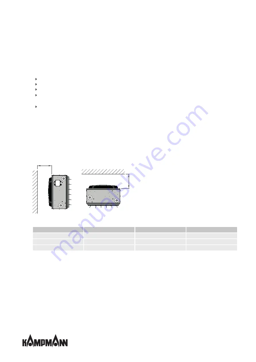
Minimum clearances
Unit heaters can be installed free-standing or suspended from the wall using the wall brackets supplied or suspended from
the ceiling using the ceiling brackets supplied. Installation using existing wall or ceiling brackets is also possible.
A minimum distance L in accordance with the table below must be respected between the suction zone of the unit and the
wall/ceiling! If you do not leave this minimum distance, the unit heater output will be reduced and the noise level will in-
crease.
Be sure to observe the minimum distances when using accessories or for maintenance purposes!
L min
L min
Fig. 2: Minimum distances, TIP
Series
Type
Minimum distance L min
Standard clearance L*
54
54_57
160 mm
285 mm
55
55_57
180 mm
285 mm
56
56_57
230 mm
335 mm
Tab. 5: Overview of types with minimum distances
* when using wall brackets, type 3_044
Summary of Contents for TIP
Page 2: ......
Page 40: ...TIP Assembly installation and operating instructions 40 12 Certificates...
Page 45: ......
Page 46: ......
Page 47: ......


