PowerKon QE
Assembly, installation and operating instructions
22
LED status messages
LED
Function
Colour
Code
Description
1
Status
Green
OFF
No voltage / Error
Flashes cyclically
Control active
Alternating fast/slow flashing
No DI1 enable
Lights up
Standby
2
Fault alarm
Red
1x flashing
EC motor fault
2x flashing
EC motor speed
3x flashing
PCB temperature sensor has triggered
4x flashing
Power reduction over 50%
5x flashing
Sensor short circuit
Lights up
STB has triggered
3
Heating
Yellow
Flashes cyclically
Electric heater PWM signal
Lights up
Electric heater 100%
Status coding of the red LED fault signal
Lights up = Continuously lit
1 x flashing = On (0.2 sec.) Off (0.8 sec.) ...
2 x flashing = On (0.2 sec.) Off (0.8 sec.) On (0.2 sec.) Off (2 sec.) ...
3 x flashing = On (0.2 sec.) Off (0.8 sec.) On (0.2 sec.) Off (0.8 sec.) On (0.2 sec.) Off (2 sec.) ...
4 x flashing = On (0.2 sec.) Off (0.8 sec.) On (0.2 sec.) Off (0.8 sec.) On (0.2 sec.) Off (0.8 sec.) On (0.2 sec.) Off (2 sec.) ...
5 x flashing = On (0.2 sec.) Off (0.8 sec.) On (0.2 sec.) Off (0.8 sec.) On (0.2 sec.) Off (0.8 sec.) On (0.2 sec.) Off (0.8 sec.) On
(0.2 sec.) Off (2 sec.) ...
Alternating = On (0.5 sec.) Off (0.2 sec.) On (0.1 sec.) Off (0.2 sec.) ...
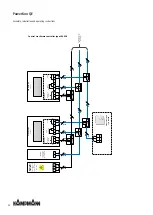
Note these points in the following layout plans for
PowerKon QE
with electromechanical control 230 V(*00):
Comply with the details on cable types and cabling with due consideration of VDE 0100.
Without *: NYM-J. The requisite number of wires, including PE conductor, is stated on the cable. Cross-sections are not
stated, as the cable length is involved in the calculation of the cross-section.
With *: J-Y(ST)Y 0.8mm. Lay separately from high voltage lines.
If other types of cables are used, they must be at least equivalent.
The terminals on the unit are suitable for a maximum wire cross-section of 2.5 mm².
We recommend type F when using RCCBs. Refer to the provisions of DIN VDE 0100 Parts 400 and 500 when configuring
the rated fault current.
Note the electrical data when rating the in-situ mains power supply and fuse.
Summary of Contents for PowerKon QE
Page 2: ......
Page 15: ...PowerKon QE Assembly installation and operating instructions 15...
Page 16: ...PowerKon QE Assembly installation and operating instructions 16...
Page 17: ...PowerKon QE Assembly installation and operating instructions 17...
Page 18: ...PowerKon QE Assembly installation and operating instructions 18...
Page 31: ...PowerKon QE Assembly installation and operating instructions 31...
Page 33: ......
Page 34: ......
Page 35: ......

