background image

Ka

Control

for Venkon

ASSEMBLY AND INSTALLATION INSTRUCTIONS

1.48

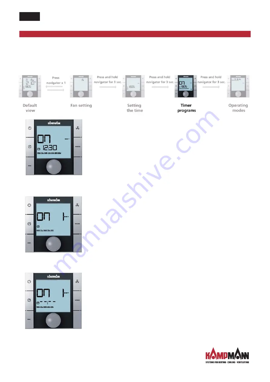
To call up the "Timer programs" selection menu, press the TIMER
key 2 x (quick access) or use the navigator.
Calling up the "Timer programs" menu using the navigator:

Step 1:

Turn the navigator to select a weekday for which you would like to 
program a switching-on or off time.
You have the option of selecting the days of the week as a block (MO-FR,
SA-SU, MO-SU) or individually.
The figure is applied by pressing the navigator (for instance: MO−FR) and
the next input screen is called up.

Step 2:

Select the number of the timer program (no. 1 or no. 2) by turning the 
navigator.
The figure is applied by pressing the navigator (for instance: Timer no. 1)
and the next input screen is called up.

Step 3:

It is possible to set 

the switching on

time you require by turning the 

navigator.
Once the minutes have been entered, press the navigator to apply the
switching-on time and the input screen for 

the switching-off

time of the

selected timer number is called up.

Venkon

16

Timer start screen

Input screen for timer number

Input screen for 

switching-on time

Summary of Contents for KaControl

Page 1: ...I393 08 10 1 GB Assembly and installation instructions Keep in a safe place for future reference 1 48 KaControl for Venkon Venkon...

Page 2: ......

Page 3: ...ontroller 29 7 3 Intake Air Temperature Sensor 29 8 Addressing 30 8 1 Single circuit Control 30 8 1 1 Maximum 6 Venkons in One Control Zone 30 8 1 2 Maximum 30 Venkons in One Control Zone 30 8 2 Multi...

Page 4: ...4 10 3 7 Function of Analog Inputs B1 B2 and B3 44 10 3 9 1 Sensor Alignment 44 10 3 10 Function of Digital Inputs DI1 DI2 DI3 DI4 and DI5 45 10 3 10 1 Digital Input DI1 45 10 3 10 2 Digital Input DI2...

Page 5: ...oisture In case of doubt discuss the application directly with the manufacturer Any use other than the uses specified above is deemed not to be correct and proper use Any damage resulting from this sh...

Page 6: ...as been switched off Caution Pipes casings and fittings can become very hot or very cold depending on the mode of operation Specialist personnel must have adequate knowledge obtained in their training...

Page 7: ...room temperature can be regulated by the user to meet the demand Product features Integral temperature sensor Large LCD multifunctional display Automatic LED background lighting Large seven segment d...

Page 8: ...Change settings Call up menus 6 MODE key Set operating modes disabled with 2 pipe applications 7 FAN key Set fan control All menus can be selected and set using the navigator The LED background lighti...

Page 9: ...et value setting enabled 9 Fan control setting Auto 1 2 3 10 Ventilation mode 11 Cooling mode 12 Heating mode 13 Automatic Heating Cooling changeover mode The symbols on the display depend on the appl...

Page 10: ...eys at the side so that the KaController with operating keys at the side is used throughout the manual for ease of understanding The different selection menus are called up either using the navigator...

Page 11: ...up for the first time the time is not shown in the default view see Setting the time selection menu Switching off the control There are 3 options for switching off the control 1 Press the ON OFF key...

Page 12: ...default view Setting the temperature setpoint A new temperature setpoint can be entered by turning the navigator in the standard view The figure is applied by pressing the navigator and the default vi...

Page 13: ...etting fan speeds Auto 1 2 3 to meet demand Pressing the navigator in default view switches the display to the Fan setting menu You can select the fan speed you require from Auo 1 2 3 by turning the n...

Page 14: ...3 Current day The Timer program selection menu is automatically called up after the current day is confirmed by pressing the navigator If no action is carried out using the navigator or function keys...

Page 15: ...of switching it on again using the ON OFF key or the navigator If no on or off time is entered into the timer matrix the Clock symbol is hidden in the default view The diagram below shows the sequence...

Page 16: ...applied by pressing the navigator for instance MO FR and the next input screen is called up Step 2 Select the number of the timer program no 1 or no 2 by turning the navigator The figure is applied by...

Page 17: ...should be replaced by Step 3 Step 4 Important note The block wise deletion of timer entries is not possible Timer entries can be overwritten at any time and this can be done for a block as well as for...

Page 18: ...al zone Heating mode The control only works in heating mode Cooling mode The control only works in cooling mode The preferred operating mode can be selected by turning the navigator in the Operating M...

Page 19: ...ervice Technician to remedy the cause of the fault 4 1 Venkon Venkon alarm table 4 2 KaController Control Electronics KaController control electronics alarm table Should more than one fault occur simu...

Page 20: ...inue to be shown on the display A fault in the motor of a slave unit is not shown on the KaController Only a fault in the motor of a master unit is shown on the KaController 5 2 Condensation Alarm The...

Page 21: ...y all BUS cables in a linear pattern Star shaped wiring is not permitted Figure on left The KaController is connected via a bus connection to the respective Venkon and must be connected to the Venkon...

Page 22: ...s with KaController incorporated into the master unit Master unit C2 control design Slave unit C1 control design inlet temperature sensor 6 2 Single circuit Control of up to 6 Units Maximum permissibl...

Page 23: ...oller incorporated in the Venkon Master unit C2 control design Slave unit C1 control design inlet air temperature sensor 6 3 Single circuit Control of up to 30 Units Maximum permissible cable lengths...

Page 24: ...in a bus line between terminals and Resistance of terminating resistor 120 Ohm 6 3 2 Bus connections between Venkons Bus communication between Venkons and CAN bus cards is solely via the CAN bus The t...

Page 25: ...up to 10 Control Circuits Maximum permissible cable lengths Total length of bus cables between the Venkon units in a control circuit see single circuit controls max 30m Total length of bus cables bet...

Page 26: ...ssing Ext Contacts e g window contact card reader etc All Venkon master units have multifunctional inputs that can be assigned different functions during commissioning Connect up the cables in accorda...

Page 27: ...Inlet Air Temperature Sensor All KaControl PCBs have analogue inputs to register the inlet air temperature There is no need to lay a separate cable to connect the inlet air temperature sensor as the c...

Page 28: ...sert the cables and connect up as per the wiring diagram Dismantle the side mullions as follows Open the operating flap Loosen the screws on the inside of the side panel Carefully raise the side casin...

Page 29: ...ing on any wiring work The bus lines should also only be connected to the KaController when the unit is fully disconnected DIP switch adjustment The DIP switches on the rear of the KaController should...

Page 30: ...re than 6 units must be addressed They are addressed by means of DIP switch settings on the CAN bus card The master unit slave unit is defined by the connection of the KaController By connecting a KaC...

Page 31: ...in one control circuit Addressing is done by means of parameter settings in the Service menu using the KaController The master unit slave unit in a control circuit is defined by the connection of the...

Page 32: ...rent software version P000 4 Select parameter P92 Access to Service level 2 by turning the navigator and enter the value P92 66 You are now in Service level 2 Enter the parameters in accordance with t...

Page 33: ...to adjust the DIP switches DIP switch settings on the PCB DIP switch no 1 Clip on sensors hot water cold water can optionally be installed to monitor the water temperatures The following functions can...

Page 34: ...ns can be locked using DIP switch no 3 The following functions are possible after setting DIP switch no 3 Switch control on off Set setpoint temperature Set fan stage All other functions such as the s...

Page 35: ...5 OFF OFF OFF must be set DIP6 ON OFF OFF Room control to clip on temperature sensor ON Room control to sensor in the KaController DIP 4 pipe Functions C1 C2 DIP1 OFF OFF Clip on temperature sensor no...

Page 36: ...p the Service menu by pressing the navigator for a minimum of 10 seconds The message Para and the CODE with the value 000 is shown on the display in sequence 3 Select the password Code 22 by turning t...

Page 37: ...can be configured via parameter P36 The base setpoint for the Setpoint setting 3 K can be configured via parameter P01 When setting the parameters P37 0 Display of setpoint temperature P36 1 Setpoint...

Page 38: ...rameter P38 can also be set for the Heating Cooling changeover via clip on sensor function Section 1 3 5 Optionally the Venkon can be switched on and off via an external potential free contact or chan...

Page 39: ...between heating and cooling the switchover can be made via a clip on sensor The clip on sensor should be ordered separately and after installation wired to the analog input B2 of the PCB as per the wi...

Page 40: ...es when the water temperature has exceeded the set limit values If the limit temperature as per P10 is not reached after at most 5 minutes the valve is closed and then reopened for 5 minutes after 4 h...

Page 41: ...arameter P51 P52 The clip on sensor can only measure the water temperature correctly in 2 pipe systems with a straight way valve if the straight way valve is cyclically opened Parameters P51 and P52 c...

Page 42: ...stage 1 after a defined idle time to record the room temperature correctly when using a clip on sensor in control configuration C2 The rinsing function is always activated when DIP switch no 6 OFF The...

Page 43: ...1 Limit Value of Water Temperature in Heating Mode Parameter P10 P11 P12 Parameters P10 P11 and P12 can be used to set the limit values for switching on the fan stages in Heating mode 10 3 7 2 Limit V...

Page 44: ...int is shown as standard in the display The measured temperature must be displayed to calibrate the sensor Parameters P37 1 must be set so that the room temperature can be displayed Room temperature s...

Page 45: ...nput DI3 The function of the digital input DI3 is specified and cannot be changed using parameters External switching is not intended as standard Parameter P43 must be set to P54 10 for digital input...

Page 46: ...ified by the DIP switch settings The function of the digital outputs No6 and No7 can be set using parameters P41 and P42 The setting for the valve PCBs to activate 0 10 V or 3 point actuators is descr...

Page 47: ...rs P41 and P42 see sections 11 3 11 1 and 11 3 11 2 Valve PCB to activate continuous valve drives 0 10V non standard models No4 Digital output 0 10 V heating cooling valve No5 Digital output 0 10 V he...

Page 48: ...t No7 on the valve circuit board heating requirement 4 0 18 P95 1 To activate the valve circuit board for 0 10 V actuators set parameter P95 1 1 0 1 P108 Reset time of PI controller to activate contin...

Page 49: ...12 Output No7 on the valve circuit board Heating valve CLOSED 12 0 18 P95 1 Set parameter P95 1 to activate the valve circuit board for 3 point actuators 1 0 1 P97 Running time of actuators for heati...

Page 50: ...m temperature Target value actual value difference 0 5 K Stage 1 Target value actual value difference 1 2 K Stage 2 Target value actual value difference 1 9 K Stage 3 10 3 12 2 Manual Fan Mode If a fa...

Page 51: ...s In 4 pipe systems the controller automatically specifies the operating mode in Automatic mode according to the room temperature and the set target value Automatic mode can be set using parameters P0...

Page 52: ...rating options or functions 72 0 255 Value Automatic operating mode 1 Cooling only operating mode 2 Real time clock 4 Ventilation only operating mode 8 Heating only operating mode 16 Automatic fan ope...

Page 53: ...the copy is successful the red LED will light up followed by the green LED Loading parameters 5 Remove the programming key and set the internal DIP switches of the programming key to Write mode DIP1...

Page 54: ...activate fan stage 2 in Heating mode 33 0 255 C Page 40 43 P012 Clip on sensor Limit value temperature to activate fan stage 3 in Heating mode 37 0 255 C Page 40 43 P013 Clip on sensor Hysteresis for...

Page 55: ...temperature 1 Display of room temperature 2 Display of sensor B2 2 Display of sensor B3 0 0 4 Page 37 P038 8 Eco Day mode changeover 26 Eco Day mode changeover changeover Heating cooling via clip on s...

Page 56: ...ls disabled in Automatic mode 1 Heating Cooling symbols enabled in Automatic mode 1 0 1 Page 44 P056 Setting of DI2 if DIP4 ON 0 Contact closed Heating Contact open Cooling 1 Contact closed Cooling Co...

Page 57: ...e is set 1 0 3 P108 Reset time of PI controller Use only with special valve PCB 0 0 255 sec 10 Page 48 49 P109 Neutral zone Use with special valve PCB 0 0 20 Min Page 48 49 P111 It is imperative that...

Page 58: ...erating steps 1 Switch off the Venkon by Pressing the ON OFF key or Pressing the navigator for a minimum of 5 seconds or Turning the navigator to the left until OFF appears 2 Call up the Parameter men...

Page 59: ...SEMBLY AND INSTALLATION INSTRUCTIONS 1 48 Venkon 59 Step Input and output Display flashes Display does not flash L01 Input B1 Sensor faulty Sensor ok L02 Input B2 Sensor faulty Sensor ok L03 Input B3...

Page 60: ...rameter menu by pressing the navigator for a minimum of 10 seconds The display shows Para and then CODE with the value 000 in sequence 3 Select the password Code 11 by turning the navigator and confir...

Page 61: ...60 C t006 LCD display contrast 15 0 15 t007 BEEP setting 0 BEEP ON 1 BEEP OFF 0 0 1 t008 Password for KaController Parameter menu 11 0 999 t009 Minimum settable setpoint temperature 8 0 20 C t010 Maxi...

Page 62: ...Notes KaControl for Venkon ASSEMBLY AND INSTALLATION INSTRUCTIONS 1 48 Venkon 62...

Page 63: ...KaControl for Venkon ASSEMBLY AND INSTALLATION INSTRUCTIONS 1 48 Venkon 63 Notes...

Page 64: ......

Reviews: