5
4
3
2
1
D
C
B
A
AMPLIFER
R171
AMP-EN
L:MUTE
C144
R172
1K
NC/22K
R176
200R
330PF/NC
C143 1uF
AMP-AUOUTL0
R173
0R
C146 1uF
R178
10K
R180
NC/0R
AMP_PWR
R186
10R
C150 1uF
C152 1uF
R187
15K
R188
6.8K
C154 1uF
C156 1uF
R189
0R
C157 1uF
AMP-AUOUTR0
R190
200R
R191
C159
NC/22K 330PF/NC
CN6
AMP-Lout+
J-B2.54-4P-L
TP1
1
TP2
1
AMP-Lout-
2
TP3
1
AMP-Rout-
3
TP4
1
AMP-Rout+
4
1
AMP_PWR
L17
0R/600ohm/100M/3A
+12V
C139
C140
C141
C142
CE7
100nf
100nf
1nf
1nf
470uF/25V/LOWESR
U14
TPA3113D2
1
SD
PVCC1
28
AMP_PWR
L27
NC
2
FAULT
PVCC2
27
3
LINP
BSN2
26
C145 220nF
L18
2
1
22uH
AMP-Lout+
4
LINN
OUTN2
25
C147
1uF/25V
5
GAIN0
PGND2
24
L28
NC
C148
6
GAIN1
OUTN1
23
1uF/25V
7
AVCC
BSN1
22
C149 220nF
L19
2
1
22uH
AMP-Lout-
8
AGND
BSP2
21
C151 220nF
L20
2
1
22uH
AMP-Rout-
C153
9
GVDD
OUTP2
20
L29
NC
1uF/25V
10
PLIMIT
PGND1
19
11
RINN
OUTP1
18
C155
L21
22uH
1uF/25V
12
RINP
BSP1
17
C158 220nF
2
1
AMP-Rout+
13
NC
PVCC3
16
L30
NC
AMP_PWR
14
PBTL
PVCC4
15
2
9
2
9
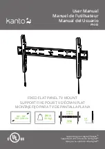
Table:Gain Setting
GAIN0(Pin 5)
GAIN1(Pin 6)
AMPLIFIER GAIN
INPUT IMPEDANCE
0
0
20dB
60 K
Ω
1
0
26dB
30 K
Ω
0
1
32dB
15 K
Ω
1
1
36dB
9 K
Ω
H/W
D
Mute
5VAIN
+12V
R174
R175
NC/0R
NC
MUTE_C
3
Q17
D3
NC/1N4148 R177
NC/2.2K
1
NC/2N3906
R179
NC/3K
D4
NC/1N4148
4.8V
2
R181
4.6V
R185
R184
CE8
+
NC/10K
NC/47K
NC/100K
NC/100uF/16V
C
Mute
L=Mute
H=Turn ON
5VAIN
+3V3STB
MUTE_C
R193
B
R208
R194
10K
1
10K
4.7K
AMP-EN
3
AMP_MUTE
R195
10K
1
Q19
R196
2N3904
2
4.7K
A
5
4
3
Size
Document Number
Rev
Custom
SHSF3201A10-101S AMP
1
Date:
Wednesday, July 30, 2014
Sheet7
of9
2
1