Standard and exclusive ceramic wood log set
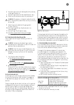
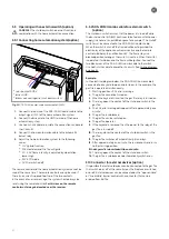
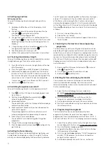
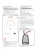
1. Place the lava stones on the ceramic burner. Ensure the
pebbles and gravel do not touch the burner and the ignition
and/or ionisation pins.
2. Cover the burner plate with chips.
Fig. 20: Non-covered ionisation pins with lava stones and chips
3. Place the wood log set according to the example in the
appendices, see: Configuration of the decorative elements
on page 42-85.
4. Remove some wires from the Kalglow set delivered with the
appliance and place these among the logs on the burner
(lava pebbles). Ensure that the Kalglow is not on top of the
ionisation and ignition pins. Kalglow gives an attractive glow
effect, the quantity can be adjusted as desired.
Placing decorative elements Kalfire GP appliances
WARNING The decorative elements must be placed
according to the instructions. It is prohibited to alter the
number of decorative elements or the configuration
thereof.
Such alterations can lead to hazardous situations in terms
of fire safety. Take the instructions into account: Safety
instructions for decorative elements on page 9.
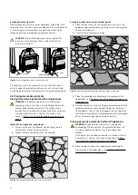
5. Place the logs and then the wood log set according to
the example in the appendices, see: Configuration of the
decorative elements on page 42-85.
Installing the technical unit
Place the technical unit in an accessible place, preferably in the
side wall of the surround. Take the choice of material into account.
A steel casing or reinforcement can negatively influence the
reception between the fireplace and remote control.
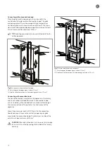
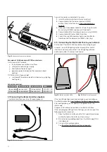
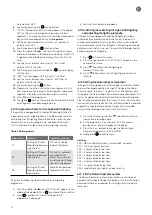
CAREFUL! The distance between the rear side of the
technical unit and the gas fire must be at least 30 cm
(without insulation).
Fig. 18: Minimum distance from the technical unit
If the technical unit is insulated with an air cavity of at least 2
cm (an air gap, for example) and three cm heat-resistant and
insulating plate material, the technical unit may be placed closer.
5.8 Placing decorative elements
Placing decorative elements Kalfire G appliances
WARNING The decorative elements must be placed
according to the instructions. It is prohibited to alter the
number of decorative elements or the configuration
thereof. Such alterations can lead to hazardous situations
with regard to fire safety. Take the instructions into
account: Safety instructions for decorative elements on
page 9
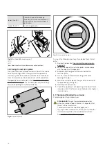
White stones, cryptonite, grey stones
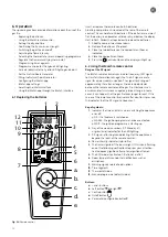
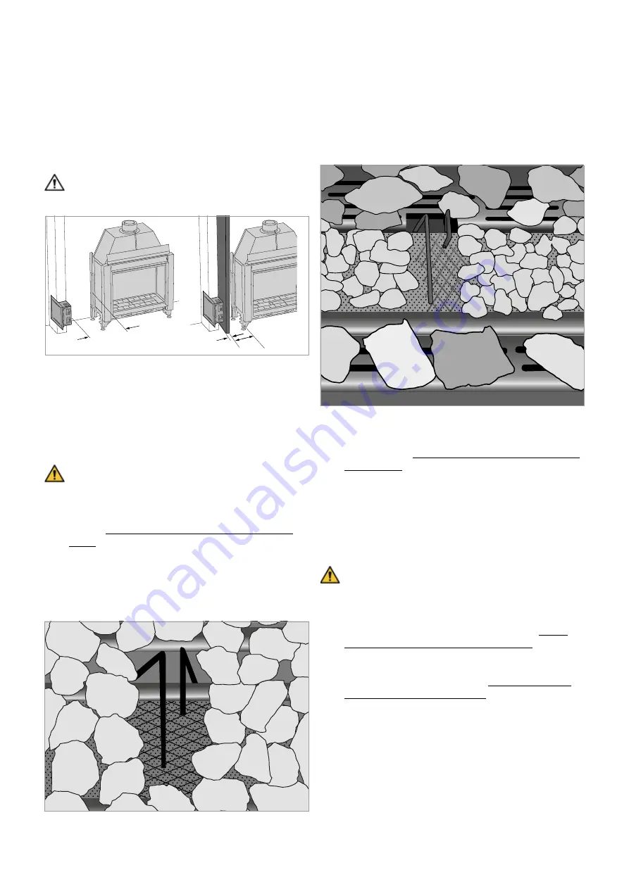
1. Place the stone set (cryptonite, white or grey) on the
ceramic burner and the burner plate.
2. Make sure the ionisation pins are not covered.
Fig. 19: Non-covered ionisation pins with white stones
min. 2 cm
min. 3 cm
min. 30 cm
20
Summary of Contents for G Series
Page 1: ...Installation instructions BALANCED FLUE GAS FIRES DON T COMPROMISE EN...
Page 2: ......
Page 4: ...4...
Page 43: ...1 4 6 7 5 2 3 43...
Page 45: ...1 3 2 5 4 6 7 8 8 7 45...
Page 47: ...1 9 4 7 3 8 5 6 2 10 47...
Page 49: ...5 1 2 3 7 4 6 8 10 9 9 49...
Page 51: ...4 5 3 6 1 1 51...
Page 52: ...7 2 7 7 2 2 8 52...
Page 54: ...4 5 2 1 1 3 54...
Page 55: ...9 8 6 7 1 55...
Page 57: ...5 6 7 8 3 2 2 1 57...
Page 58: ...9 4 4 8 58...
Page 60: ...5 2 9 6 2 1 4 3 60...
Page 61: ...7 7 10 11 8 61...
Page 63: ...1 7 7 3 4 6 2 7 63...
Page 64: ...2 4 4 5 5 8 64...
Page 66: ...7 4 5 6 1 8 9 66...
Page 67: ...3 3 11 2 10 10 12 67...
Page 69: ...1 2 6 6 8 8 9 7 7 4 With gas type G30 log 4 to be placed at extreme right 3 4 5 11 69...
Page 72: ...10 2 1 9 11 3 3 4 5 5 7 6 72...
Page 73: ...13 12 12 12 8 73...
Page 76: ...3 1 6 5 4 2 13 76...
Page 77: ...14 7 10 11 8 12 12 Other side Divide 15 cryptonite and 16 ash 77...
Page 80: ...3 4 5 7 1 3 4 5 6 1 4 5 1 3 4 1 3 2 1 2 3 1 3 1 2 4 5 1 6 2 6 7 14 12 11 11 3 80...
Page 81: ...3 4 5 7 8 1 3 4 7 9 10 8 3 4 5 6 7 8 1 3 4 5 6 7 8 1 3 4 5 6 7 1 9 10 8 15 13 81...
Page 84: ...4 3 5 2 3 4 5 1 2 3 4 5 1 1 2 3 4 1 1 2 1 1 1 2 1 1 1 1 1 2 3 4 5 6 6 1 1 1 14 11 84...
Page 94: ...94...
Page 95: ...95...
Page 96: ...Gelo rveldweg 21 5951 DH Belfeld info kalfire nl KALFIRE COM DON T COMPROMISE REF V01 2019 EN...


