


5.2 Placing the gas fire
Place the rear wall taking the material into account.
See: Installation Instructions on page 8. Then place the gas fire
at the desired location. Mount the legs and finish the rear wall as
indicated in the following paragraphs.
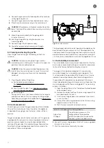
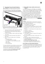
5.2.1 Fitting and mounting the gas fire
The gas fire is placed on four adjustable support legs. The support
legs on the glass side of the gas fire need to be precisely sawn off
before they can be mounted.
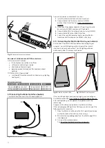
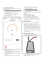
When the bolts are mounted against the rear wall, a space of
a minimum of two cm is created between the rear side of the
appliance and the rear wall.
CAREFUL! It is no longer possible to adjust the glass once
the surround has been finished. Should the mounting of a
modified glass as a result of the incorrect placement of the
original glass be required, this will fall outside of the factory
warranty.
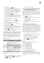
Fig. 5: Setting support legs
Carry out the following steps to set and assemble the gas fire:
1. Place the front glass in the appliance.
2. Unscrew two bolts (A) from each support leg.
3. To ensure that the support legs are on the desired height,
you might have to saw the top off the support legs.
4. If necessary, place the support legs in the designated
holder.
5. Set the approximate height.
6. Screw the two bolts (A) back on.
7. Set the exact height of the gas fire by adjusting the
tightness of the bolts on each leg (B). The range of
adjustment is 3 cm.
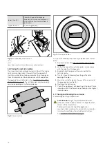
8. Set the gas fire to spirit level by tightening or loosening the
bolts on each support leg.
9. Adjust the wall clamp, leaving a minimum of
2 cm between the gas fire and the wall.
10. Secure the gas fire to the wall using the
previously mounted clamps.
Fig. 6: Mounting gas fire to wall
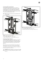
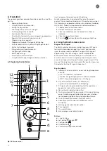
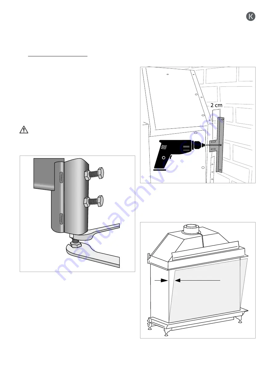
11. Check whether all four front glass corners align with the
side glass. The twisting and turning that was necessary
while setting and adjusting the gas fire, may have caused
the front and the side glass to become misaligned.
Fig. 7: Check alignment front glass.
12. Set the gas fire accurately by adjusting the legs, so the
glass properly aligns.
2 mm max.
A
A
B
B
15
Summary of Contents for G Series
Page 1: ...Installation instructions BALANCED FLUE GAS FIRES DON T COMPROMISE EN...
Page 2: ......
Page 4: ...4...
Page 43: ...1 4 6 7 5 2 3 43...
Page 45: ...1 3 2 5 4 6 7 8 8 7 45...
Page 47: ...1 9 4 7 3 8 5 6 2 10 47...
Page 49: ...5 1 2 3 7 4 6 8 10 9 9 49...
Page 51: ...4 5 3 6 1 1 51...
Page 52: ...7 2 7 7 2 2 8 52...
Page 54: ...4 5 2 1 1 3 54...
Page 55: ...9 8 6 7 1 55...
Page 57: ...5 6 7 8 3 2 2 1 57...
Page 58: ...9 4 4 8 58...
Page 60: ...5 2 9 6 2 1 4 3 60...
Page 61: ...7 7 10 11 8 61...
Page 63: ...1 7 7 3 4 6 2 7 63...
Page 64: ...2 4 4 5 5 8 64...
Page 66: ...7 4 5 6 1 8 9 66...
Page 67: ...3 3 11 2 10 10 12 67...
Page 69: ...1 2 6 6 8 8 9 7 7 4 With gas type G30 log 4 to be placed at extreme right 3 4 5 11 69...
Page 72: ...10 2 1 9 11 3 3 4 5 5 7 6 72...
Page 73: ...13 12 12 12 8 73...
Page 76: ...3 1 6 5 4 2 13 76...
Page 77: ...14 7 10 11 8 12 12 Other side Divide 15 cryptonite and 16 ash 77...
Page 80: ...3 4 5 7 1 3 4 5 6 1 4 5 1 3 4 1 3 2 1 2 3 1 3 1 2 4 5 1 6 2 6 7 14 12 11 11 3 80...
Page 81: ...3 4 5 7 8 1 3 4 7 9 10 8 3 4 5 6 7 8 1 3 4 5 6 7 8 1 3 4 5 6 7 1 9 10 8 15 13 81...
Page 84: ...4 3 5 2 3 4 5 1 2 3 4 5 1 1 2 3 4 1 1 2 1 1 1 2 1 1 1 1 1 2 3 4 5 6 6 1 1 1 14 11 84...
Page 94: ...94...
Page 95: ...95...
Page 96: ...Gelo rveldweg 21 5951 DH Belfeld info kalfire nl KALFIRE COM DON T COMPROMISE REF V01 2019 EN...


