KAKA Industrial BS-106G Assembly & Operating Manual Download Page 5

4

1.3 Emergencies according to European Standard “2006/42/EC”.

In the event of incorrect operation of danger conditions, the machine may be stopped

immediately by pressing the red emergency button.

The casual or voluntary removal of the blade cover of the flywheels causes the

stepping-in of a interlock switch that automatically stops all machine functions.

Note: resetting of machine operation after each emergency stop require specific

restart button.

2. DESCRIPTION OF MACHINE

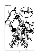
2.1 Description of machine and its components

The band sawing machine produced by us has a sturdy frame made from welded and

painted sheet-steel. The upper surface is designed to allow the complete draining

away of the cutting fluid. The band holding bow is made of cast-iron and has generous

dimensions

providing the cutting unit with the necessary strength and precision. The

vice unit is made of cast-iron and clamps the material to be cut securely. The bar-stop

device allows the length required to be preset and a constant level of performance for

repeated cuts. The blade-holding bow is firmly attached to a reduction unit built onto

the motor and to the base by means of a joint which allows 60° rotation to the right.

This joint also allows the cutting movement to advance manually or by falling.

The coolant pump is fitted to the machine base. The main switch is located on the

front panel. The choice of one of the two motor rotation speeds and therefore cutting

speed is carried out by the main switch. The front panel is also fitted with an

emergency stop button and a START button. The control lever

fitted with an

ergonomic hand-grip and activation button with safety release action, reduces fatigue

during operation to a minimum. The blade is protected by a guard with interlock which

covers the upper area and the hand wheels and by two adjustable lower guards which

protect the operator from ejected shavings and coolant. The machine is supplied with

a set of service spanners.

2.2 Intended and unsuitable uses of machine

The band sawing machine has been designed and built to cut bars, structural steel

and ferrous metal pipes in accordance with the instructions contained in this manual.

Therefore, the cutting of other materials is not permitted: if the above

recommendations are not observed

the machine could be damaged and the health

and safety of the operator put at risk. Cutting is not permitted, if the bar has not been

first locked in the vice.

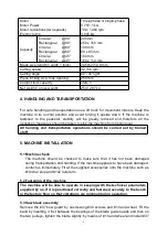
3. MAIN TECHNICAL DATA

Under no circumstances should the following data be altered, this is in order to protect

the correct functioning of the machine and to avoid creating safety risks for the

operator.

Summary of Contents for BS-106G

Page 1: ...0 METAL CUTTING BAND SAW MODEL BS 106G Assembly Operating manual...

Page 2: ...s of the machine 4 3 Main technical date 4 4 Handling and transportation 5 5 Machine installation 5 5 1 Machine check 5 5 2 Fastening of the machine 5 5 3 Saw blade assembly 5 5 4 Electrical connectio...

Page 3: ...assistance to the operator has been high lighted The Operating instructions are an integral part of the machine and should be consulted before during and after the start up of machine and whenever els...

Page 4: ...ing like shirts with sleeves that are too long gloves that are too big bracelets chains or any other objects that could get caught in the machine during operation Tie back long hair K Keep the area fr...

Page 5: ...ws the cutting movement to advance manually or by falling The coolant pump is fitted to the machine base The main switch is located on the front panel The choice of one of the two motor rotation speed...

Page 6: ...ures should be taken to stop the machine from tipping over All handing and transportation operations should be carried out by trained staff 5 MACHINE INSTALLATION 5 1 Machine check The machine should...

Page 7: ...heel to avoid the slackening of the band B Check that the hand indicates the required cutting angle vice scale C Make sure that the bow and the vice are locked by means of 136 lock handle D With the m...

Page 8: ...ges 6 3 SPECIAL SAFETY CHECKS A Before using the machine check carefully that the safety devices are in good working order that the mobile parts are not blocked that no parts are damaged and that all...

Page 9: ...itioned the nearest possible to the piece to be cut Check every 3 months the existing tolerance between the blade guides making sure that it does not exceed the blade thickness of one tenth of a milli...

Page 10: ...on the band saw machine identical to the machine to which these operation instructions refer has given the following results ACOUSTIC RADIATION PRESSURE 1 LAeq 83 2 dB A 2 LAeq 90 6 dB the maximum acc...

Page 11: ...Press block 1 57 Blade guide eccentric bush 2 19 Hex cap bolt M6X30 2 57 1 Nut M8 1 20 Bolt M8X25 4 57 2 Bolt M8X30 1 21 Bolt M6X30 4 57 3 Nut M8 1 22 Bearing 608 2Z 4 57 4 Bolt M8x25 1 23 Blade guide...

Page 12: ...seat 1 92 Upper vice 1 131 Washer 4 93 Vice plate 1 132 Bolt M10X25 4 94 Bolt M8X20 2 133 Ring 3 55 x 288 1 95 Bolt M8X25 3 134 Bolt M6X10 1 96 Nut 8 3 135 Link axis 1 97 Wedge plate 1 136 Bench lever...

Page 13: ...2 27 2 12 11 6 9 8 7 6 5 4 3 12 2 1 57 4 57 3 57 2 57 1 54 2 54 1 2 68 67 2 66 2 65 22 4 21 4 20 4 19 6 16 2 15 2 39 2 38 2 37 36 35 34 33 32 2 31 29 2 30 28 26 2 25 24 4 23 4 48 47 46 2 44 43 42 41 4...

Page 14: ...148 2 152 4 153 4 142 146 4 144 4 143 4 145 151 102 2 101 4 99 100 4 110 5 108 109 98 97 96 3 95 3 94 2 93 92 87 85 91 90 89 2 83 88 86 84 82 81 112 113 115 116 117 127 2 123 126 125 2 124 120 80 118...

Page 15: ...14 11 ELECTRIC DRAWING...

Page 16: ...This manual is only for your reference Owning to the continuous improvement changes may be made at any time with no obligation on the part of machine And please note the local voltage for operating m...

Reviews: