background image

8

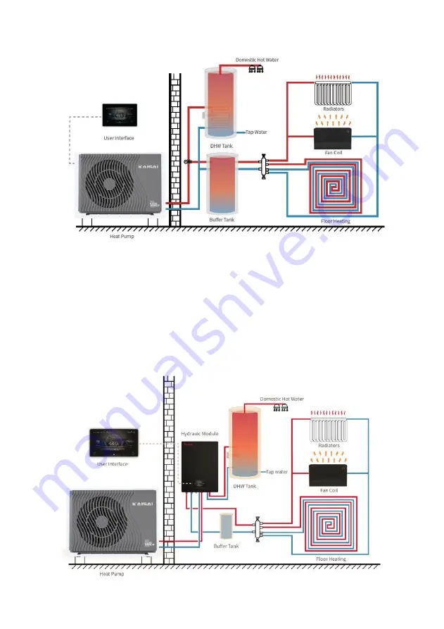
5.2 Installation with Hydronic Module

KAISAI provides the monoblock heat pump (without circulation pump) and

the Hydronic box. Hydronic box includes one small size built-in buffer tank,

one main circulation water pump, one space heating/cooling circulation

water pump, one DHW pump, a safety valve, a water charge valve and an

expansion tank, electrical heater. When installing the unit, installers should

connect the heat pump directly to the Hydronic box while the buffer tank (for

space heating/cooling) is considered whether to be added or not. Storage

water tank is needed for the domestic hot water application. Temperature

sensor should be added in the storage water tank.

Summary of Contents for KHX-09PY1

Page 1: ...TECHNICAL MANUAL SERIA R290...

Page 2: ...n mm 6 5 Installation Diagram 7 6 Handling Installation 9 7 Maintenance 15 8 Parameters 18 9 Operation Range 20 10 Explosion View 23 11 Wiring Diagram 34 12 Display Operation Guide 37 13 Electrical Pa...

Page 3: ...tions are adhered to at all times to keep the warranty The unit can only be opened or repaired by a qualified installer or an authorized dealer Maintenance and operation must be carried out according...

Page 4: ...refully and understand the following information correctly Mark Meaning WARNING A wrong operation may lead to death or grievous injury on people ATTENTION A wrong operation may lead to harm to people...

Page 5: ...rong or strange smells the power supply needs to be shut off to stop the unit Continue running may cause short circuit or fire Move and Repair Meaning Entrust When the heat pump needs to be moved or i...

Page 6: ...Installation Place The unit CANNOT be installed near the flammable gas Once there is any leakage of the gas fire may occur Fix the unit Make sure that the basement of the heat pump is strong enough to...

Page 7: ...the heat pump Centralized controlling system can control several units by PC 3 2 Nice Appearance The heat pump is designed with beautiful looking The monoblock one has the water pump included which is...

Page 8: ...6 4 Unit Dimension mm 4 1 Models KHX 09PY1 4 2 Models KHX 14PY3...

Page 9: ...a main circulation pump built inside When install the unit installers should connect the heat pump with other parts including the buffer tank for space heating cooling storage water tank for domestic...

Page 10: ...cooling circulation water pump one DHW pump a safety valve a water charge valve and an expansion tank electrical heater When installing the unit installers should connect the heat pump directly to th...

Page 11: ...s a Plate heat exchanger Use the SWEP efficient heat exchanger with small size and high efficiency b Environmentally friendly refrigerant Use the new generation of environmentally friendly refrigerant...

Page 12: ...ating Cooling including Buffer tank 1 Heat pump 10 Relief valve 19 PT valve 2 Flexible pipe 11 Air vent valve 20 Electrical heater 3 Thermometer 12 Water pump for floor heating 21 Hot water sensor 4 M...

Page 13: ...source water heat pump is used for house office hotel and so forth which need heating or cooling separately with each area needed to be controlled 6 3 Installation Method The heat pump can be installe...

Page 14: ...ction of the switch is normal and controlled by the controller 6 Try to avoid air stayed inside of the water pipe and there must be air vent on the top point of the water loop 7 There must be thermome...

Page 15: ...vent damage to the heat pump cabinet See picture 1 Picture 1 DO NOT touch the heat exchanger of the heat pump with fingers or other objects WARNING 6 9 Trial Running 6 9 1 Inspection before trial runn...

Page 16: ...l be 0 2 MPa on the water pressure meter 2 When the water pump runs for 1 minutes the compressor will start Hear whether there is strange sound from the compressor If abnormal sound occurs please stop...

Page 17: ...r Ensure the water refill and exhaust device in the waterway is well otherwise the performance and reliability of the unit will become worse Ensure the waterways are clean and avoid dirt and blockage...

Page 18: ...fire and explosion Ensure that space is sufficiently aerated around the product Preparation Before maintenance please ensure that the unit stop running and cut off the power supply Inspection and clea...

Page 19: ...duct using a sponge and hot water with a cleaning agent Do not use abrasive cleaners Do not use solvents Do not use any cleaning agents that contain chlorine or ammonia 7 3 3 Checking the evaporator f...

Page 20: ...Flow m3 h Refrigerant Proper Input kg CO2 Equivalent Ton 1 Sound Pressure 1m dB A 43 Sound Power Level EN12102 dB 57 Net Weight kg 103 Operation Pressure Low Side MPa 0 8 Operation Pressure High Side...

Page 21: ...n Motor Power Input min max W 30 80 Fan Speed RPM RPM 220 600 Water Connection inch inch 1 Water Pressure Drop max kPa 20 Circulation Pump Head m 9 Cabinet Type Galvanized sheet ASA Galvanized sheet A...

Page 22: ...2 08 2 15 2 15 2 17 2 19 2 22 2 17 2 17 2 02 2 05 2 09 1 95 1 96 1 93 1 78 1 60 1 61 50 1 93 1 98 2 14 2 20 2 22 2 27 2 28 2 31 2 26 2 27 2 15 2 15 2 20 2 05 2 05 2 05 1 90 1 72 1 73 55 1 97 2 04 2 21...

Page 23: ...3 07 2 82 2 44 2 47 45 3 11 3 21 3 46 3 58 3 58 3 61 3 65 3 69 3 61 3 61 3 36 3 41 3 47 3 25 3 26 3 22 2 95 2 66 2 68 50 3 20 3 30 3 56 3 67 3 68 3 78 3 80 3 84 3 77 3 77 3 57 3 57 3 65 3 41 3 41 3 41...

Page 24: ...5 23 5 25 5 26 4 62 4 65 4 69 4 31 3 74 3 79 45 4 68 4 82 5 20 5 37 5 43 5 47 5 53 5 62 5 50 5 50 5 12 5 20 5 30 4 96 4 97 4 91 4 52 4 07 4 10 50 4 82 4 96 5 34 5 50 5 59 5 73 5 76 5 85 5 73 5 74 5 45...

Page 25: ...23 10 Explosion View Model and code KHX 09PY1 13100104 A Whole Unit Exploded Diagram B Electric Box Exploded Diagra...

Page 26: ...er pump bracket 1 12 81500460 Inlet water pipe 1 13 71301984 Plate heat exchanger 1 14 80711315 Panel support 1 15 2001 1418 Four way valve 1 16 80715367 Plate heat exchanger support 1 17 81000043 Shu...

Page 27: ...ector 1 39 80716287 Left side net 1 40 80712920 Column assembly 1 41 80901771 Top cover 1 42 80716290 Top beam 1 43 80711322 Waterproof cover panel of electrical box 1 44 80717593 Electrical box 1 45...

Page 28: ...26 No Part Code Part Name Qty 55 20000 220310 316 Cable clamp 1 56 2000 3928 3 Position terminal block 1 Model and code KHX 14PY3 13110166 A Whole Unit Exploded Diagram...

Page 29: ...ting 1 5 81500469 Inlet water pipe fitting 1 6 80400092 Water pump 1 7 81500470 Water pump fitting 1 8 80718910 Right rear side panel 1 9 20000 140485 Four way valve 1 10 2004 1444 Filter 2 11 8100004...

Page 30: ...Compressor cover 1 28 80711974 Compressor cover 4 29 80711976 Compressor cover 1 30 80711966 Air deflector 1 31 80901247 Front frame 1 32 80708055 Fan grille 1 33 80200153 DC motor 1 34 20000 270073...

Page 31: ...rive module 1 49 20000 430215 BHB21 1 50 20000 360297 Relay 1 51 80900483 Plastic base 1 52 82300074 Filter board 1 53 20000 390077 Fuse terminal 3 54 83100033 Fuse 1 55 2000 3909 2 Position terminal...

Page 32: ...30 Model and code KHX 16PY3 13130199 A Whole Unit Exploded Diagram B Electric Box Exploded Diagra...

Page 33: ...85400021 Standard clamp 1 11 80714403 Rear side panel 1 12 81700132 Rubber feet 4 13 80714394 Chassis 1 14 80714398 Suspension chassis 1 15 80100187 Compressor 1 16 80714395 Middle partition 1 17 8071...

Page 34: ...at exchanger 1 39 80709607 Motor support 1 40 80709628 Electrical box cover 1 41 80714397 Electrical box 1 42 82500015 Reactor 1 43 80714400 Water pump support 1 44 81500584 Outlet water pipe 1 45 200...

Page 35: ...Code Part Name Qty 56 20000 390180 5 Position terminal block 1 57 82300314 PC4003 G 1 58 80900483 Plastic base 1 59 82300485 ZL0001 G 1 60 82300381 Variable frequency drive module 1 61 82300074 Filte...

Page 36: ...5A 5 6 CWU w wy Zaw r 3 drogowy Pompa ciep ej wody Grz Ch w wy 8 7 10 9 27 28 10 9 Zabezp termiczne 1 2 3 4 5 6 7 8 11 12 N1 L1 L2 13 14 6 8K RT 13 14 29 30 26 Grza ka elektryczna 220V 1 stopie Grza k...

Page 37: ...39 40 RED WHT 33 35 37 39 33 BLK YEL BLK BLU RED 41 3 1 4 2 5 6 7 8 03 S S N S1 S2 S 32 12V1 21 K11 K11 CH CH S S 3 7 20 N N EEV 5 R N N WHT RED BLK YEL 4 12V RED 42 FU 250mA U V W U V W CC1 GND1 GND...

Page 38: ...2 3 4 5 6 7 8 11 12 13 14 6 8K RT 13 14 43 4 BLK YEL 34 35 36 37 38 39 40 RED WHT 33 35 37 39 33 YEL BLK BLU RED 41 1 3 4 2 5 6 7 8 03 S S N S1 S2 S 25 FM2 CN4 5V K11 PH N S S R N N 42 CH K11 29 30 1...

Page 39: ...37 12 Display Operation Guide 12 1 Main Interface Display and Function 1 Power on Interface 2 Starting up Interface...

Page 40: ...ing the main interface 3 is tank water temperature The machine is in hot water mode when this icon is shown Otherwise this icon is not shown 6 is outlet water temperature or room temperature If H25 0...

Page 41: ...off key can start up the machine 2 In starting up interface on off key is in blue status press on off key can shut down the machine 12 2 1 Mode switch There are five modes can be selected after slidi...

Page 42: ...ter function the key of hot water mode function will not be displayed In the main interface there are five modes that can be selected after tapping the mode key 1 tapping hot water mode icon then the...

Page 43: ...troller back to main interface 2 Sliding 2 the target temperature can be adjusted in the clockwise or counter clock wise direction 3 Tapping 3 the target temperature can be saved 12 3 1 Unlock screen...

Page 44: ...ed 12 4 Setting interface display and function Swipe from right to left on the main interface to enter the function setting interface and swipe from left to right on the function setting interface to...

Page 45: ...parameters interface 3 Curve key Click this key to view the temperature curve 4 Adjust brightness Click this button to adjust screen brightness 5 Fault Click to view fault history 5 One key electric...

Page 46: ...nitialized to the time at the moment when the system time setting button is pressed and you can adjust the time by sliding up and down Note When the temperature unit is the time format is displayed as...

Page 47: ...t from 0 00 23 59 The mute timer off setting point select from 0 00 23 59 The status of mute timer on Enable Blue Disable Gray The status of mute timer on is shown The status of mute timer off Enable...

Page 48: ...lected and saved every five minutes Timekeeping is made from the latest data saving if the power is disrupted when the time is less than five minutes the data during such period will not be saved 3 On...

Page 49: ...tness setting value 3 The screen has the function of automatic on and off if there is no operation for 30s the screen will enter the half time screen state 4 If there is no operation for another 5 min...

Page 50: ...12 5 Status interface display Swipe from left to right on the main interface to enter the status interface and swipe from right to left on the status interface to return to the main interface The stat...

Page 51: ...e Fault name Occurrence time of the fault Day an month hour minute second Note If the current temperature is occurrence time of the fault Month and day hour minute second Click this key to clear all f...

Page 52: ...imum Evaporation Temp of Cooling 50 30 10 50 30 A26 Refrigerant Type 0 R32 1 R290 0 0 R32 1 R290 A27 Temp Diff of Limiting Frequency 20 20 7 A28 Temp Diff Between Outlet and DHW Temp 20 20 7 A29 Enabl...

Page 53: ...25 75 2 Grundfos 25 105 3 Grundfos 25 125 0 0 No Flow Detection 1 Grundfos 25 75 2 Grundfos 25 105 3 Grundfos 25 125 H32 Force Switch Mode Time 1 300min 120min 1 120min H33 Fan Motor Driver and Comp...

Page 54: ...le 3 DC 3 F02 Coil Temp for Max Fan Speed in Cooling 15 0 60 0 50 F03 Coil Temp for Min Fan Speed in Cooling 15 0 60 0 10 F05 Coil Temp for Max Fan Speed in Heating 15 0 60 0 10 F06 Coil Temp for Min...

Page 55: ...110 D05 1 Defrosting Suction Pressure 1 0 45bar 2 6bar D05 2 Defrosting Suction Pressure 2 0 45bar 1 7bar D06 Defrosting Cycle Time Correction 0 120min 15 min D07 Ambient Temp of Start Sliding Defrost...

Page 56: ...emp Diff of Exiting Over high Outlet Temp 0 15 2 R16 Temp Diff for Power on in DHW 0 10 5 R17 Temp Diff for Standby in DHW 0 10 2 R29 Low AT for Water Temp Limit On R30 4 5 R30 Low AT for Water Temp L...

Page 57: ...r pump 0 Normal 1 Special 2 Intermittent 0 Normal 1 Special 2 Inter mittent 2 P02 Circulating water pump operation interval 1 120min 30 Min Non zero P03 Circulating water pump operation duration 1 30m...

Page 58: ...the display whether shown locked icon Check the cable Reconnect the power cable and check if it works Heating effect is not good The compressor running low frequency The fan is not running or speed i...

Page 59: ...water inlet 4 It is the protection in winter Once the water temperature rises up to 8 o C or the ambient temp is higher than 1 o C the error code disappears E29 Secondary Anti freezing Protection Amb...

Page 60: ...k the input voltage of R S T on compressor driver board if lower than 210V it will get this protection 3 If they are OK please replace a new compressor driver board F07 AC Input Under voltage 1 Measur...

Page 61: ...GBT Power Device Overheat Alarm 1 Check the fans are running or not 2 Check the installation distance and space 3 If they are OK please replace a new compressor driver board 4 Leave enough distance an...

Page 62: ...00 or higher than 500k please replace a new one P02 Water Outlet Temp Sensor Fault P04 Ambient Temp Sensor Fault P17 Water Outlet Temp Sensor Fault P032 Hot Water Tank Temp Sensor Fault P42 Room Temp...

Page 63: ...When the display is 25 the data transmitted by the protocol is 250 when bit15 is 1 it represents a negative number and when bit15 is 0 it represents an integer when this value is 32767 it indicates t...

Page 64: ...ture difference read write 1 0 10 TEMP1 1173 03 06 R05 Use of electric heating read write 0 0 No electric heating 1 water circuit electric heating 2 water tank electric heating DIGI1 1174 03 06 R35 Co...

Page 65: ...nt temperature value after compensation for heating mode only write TEMP1 2019 16 O01 023 write bit0 O01 System 1 compressor output 0 OFF 1 ON bit1 Reserved bit2 O03 Fan high speed output 0 OFF 1 ON b...

Page 66: ...erved bit8 Reserved bit9 S10 A C switch 0 C ON 1 C OFF bit10 Reserved bit11 Reserved bit12 Reserved bit13 Reserved bit14 Reserved bit15 Reserved DIGI1 2045 16 T01 Water inlet temperature write Measure...

Page 67: ...Input voltage sampling failure bit12 Communication failure between DSP and PFC bit13 Drive board temperature sensing failure bit14 Communication failure between DSP and communication board bit15 Comm...

Page 68: ...served bit11 Reserved bit12 Reserved bit13 Reserved bit14 Reserved bit15 Reserved DIGI1 2085 16 write bit0 Reserved bit1 Reserved bit2 Heating return water temperature sensing failure 0 no 1 yes bit3...

Page 69: ...peed limit 0 no 1 yes bit4 Fan 2 overload speed limit 0 no 1 yes bit5 Protection for excessive water temperature difference between inlet and outlet 0 no 1 yes bit6 Protection against excessive outlet...

Page 70: ...re 0 no 1 yes bit10 Reserved bit11 Reserved bit12 System 1 anti freezing protection for 3 times or more 0 no 1 yes bit13 Reserved bit14 Reserved bit15 Reserved DIGI1 2088 16 write bit0 System 1 exhaus...

Page 71: ...sensing failure 0 no 1 yes bit3 Ambient temperature sensing failure 0 no 1 yes bit4 System 1 return air temperature sensing failure 0 no 1 yes bit5 System 1 anti freezing 1 temperature sensing failur...

Page 72: ...t3 Reserved bit4 Reserved bit5 Reserved bit6 Reserved bit7 Reserved bit8 Water tank temperature sensing failure 0 no 1 yes bit9 Reserved bit10 Reserved bit11 Fan 1 failure 0 no 1 yes bit12 Fan 2 failu...

Reviews: