4
GB
APPLICATION CONDITIONS
Support Frame
Several different types are available, depending
on the desired installation.
The structures supplied support snow loads of
1200 Pa and wind loads of 900 Pa (130 km/h)If
necessary, request the assistance of an expert in
structural loads.
Support Structure:
Qualified person to inspect and ensure that
the installation structure can support the
installation of the support frame and solar
system. Strengthening of the structure may be
required.
Maximum operating pressure
The collector has a maximum operating
pressure of 8 bar.
Minimum and maximum angle of inclination
The collector can be installed with an inclination
of between 15° and 35°.
All collector connections
and breather holes must be protected from
infiltration of water and dirt.
Collector inclination will normally be determine
by the roof pitch, or the pitch of the support
frame used. Please refer to the specific mounting
system for more information.
Formation of condensation
Early in the morning or late in the afternoon, the
glass on the panel may steam up on the inside
or experience condensation on the outside.
The damper the air, the greater the likelihood of
condensation occurring.
If it does form, the condensation should
gradually disappear as soon as suitably sunny
conditions are created.
The phenomenon does not jeopardize the
correct operation of the system.
Transportation and handling
• The solar collector should be transported
in an upright position, avoiding sudden
movements.
• During transportation, particular care should
be taken when positioning the glass side. Do
not place the collectors so that the glass is
facing downwards or transport them in this
manner.
• Before installing the solar collector, never
leave it exposed to the elements with the
glass side facing downwards; if it rains, water
could enter the collector. This would cause
condensation to form inside the panel.
• Leave the collectors in their packaging until
they reach the place where they are to be
installed; this will prevent damage.
• Do not rest the rear side of the collectors on
uneven or pointed surfaces.
• Always keep the glass side of the collector
covered until the system is ready for
operation.
Orientation
The solar collectors offer maximum energy
performance when the surfaces are facing
directly the equator (therefore directly south
for Northern Hemisphere installations and
directly north for Southern Hemisphere
installations). Different local conditions, for
example the amount of shade or the direction
of the roof slants, may lead to a slight variation
of the equator-facing position (the maximum
recommended variation is 30° in relation to the
equator).
Positioning
Before installing the solar collector you must
choose its position, so that the following
conditions are satisfied:
• the collector must be placed in areas that are
not in the shade during hours of sunlight;
• there must be minimal wind exposure;
• it must be placed as close as possible to the
storage cylinder;
• it must be accessible for any necessary
maintenance work;
• it must be firmly secured in place and able to
withstand wind pressure;
• in order to minimise wind loads, avoid
installing the appliance on roof edges.
Minimum distance: 1.2 m; increase this
distance for tall buildings and heavily
exposed areas.
Earthing system and anti-lightning
protection
The metal piping used in the solar heating
circuit and parts that carry electricity must
be proportionally connected to the general
earthing system, with a green/yellow copper
wire with a minimum section of 16 mm² (H07
VU o R). If an anti-lightning system is in place,
the collectors can be connected to it. The earth
connection may be performed using an earth
rod. The earth conductor must be installed
outside the building. The ground electrode
must be connected to the general earthing
system using a proportionate wire of the same
section.
Work must only be carried out by a company
specialising in electrical circuitry.
Warning
Hot water supplied at a temperature above
50°C to the taps at the point of use could cause
immediate serious scalds. Children, the disabled
and the elderly are more exposed to this risk. We
therefore recommend the use of a thermostatic
mixer valve screwed onto the appliance water
outlet pipe.
This device shall be able to withstand the
maximum possible domestic hot water
temperature from the solar system. (110 ° C).
Stagnation Behaviour
The THERMO DR-2 resistance to overheating has
been tested according to 5.2 of EN 12976-2:2017
with extremely sunny climate conditions; these
systems are therefore suitable for the climate
class type A+ (according to ISO 9806:2018).
Low temperature behaviour
Heat radiating towards a cold night sky
may cause frost-related damage, even at air
temperatures of 5°C.
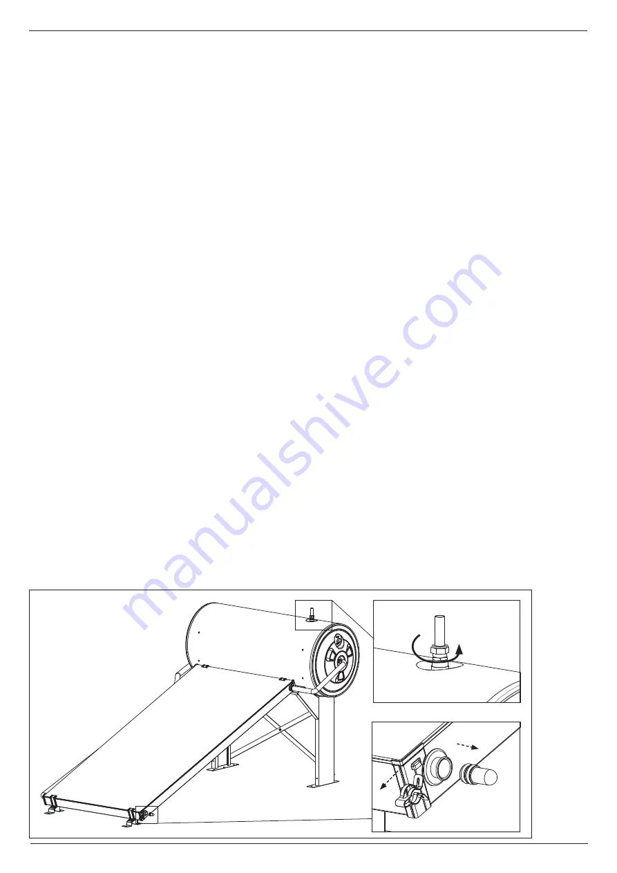
If the temperature falls below 5°C, drain the
system as follows:
1) Close the cold water supply
2) Open a hot water tap downward the solar
system
3) Open the hot water outlet (Fig.1 A) of the
tank to allow air to go inside
4) Dismount the hydraulic closure (Fig.1 B) of
the collector to drain the system
5) When the system is drained, close the hot
water tap downward the solar system
6) Close the hot water outlet of the tank
7) Mount the hydraulic closure of the collector
8) When it will be necessary to restart the system
, please refer to the section “Preparation of
the system for operation” an following.
B
A
Fig.1
Summary of Contents for THERMO DR-2
Page 10: ...10 GB...
Page 11: ...11 GB...


