Kair KHRV150/12RH Installation & Maintenance Instructions Manual Download Page 6

Page

5

j)

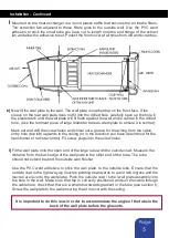
Mounted on the heat exchanger is a round plastic baffle that secures the air intake filters.
The  extraction  fan  adjacent  to  these  filters  goes  to  the  outside  wall.  Use  the  PVC  weld
adhesive to stick the small tube you have cut to length onto the end flange of the extract
fan and allow the adhesive to set. Protect the front cover at all times from dirt and scratches.

Installation -

Continued

k)

Now fit the wall plate to the wall. The wall plate is marked top on the front face. If the
sleeve on the rear wall plate does not fit into the drilled hole, carefully open up the hole in
the plasterwork until the wall plate will fit flush against the wall and is central in the drilled
hole. (Use the remnant piece of large diameter tube as a template to ensure it is central).

Mark out and drill the screw holes and chisel out a groove for the wiring from the cable
entry hole (top left) upwards to the ceiling (or in the direction you have determined for the
transformer or remote control). Fit screw plugs into the screw holes.

l)

Fit the wall plate onto the open end of the large tube with the outside cowl. Measure the
distance from the back edge of the wall plate to the other end of the tube. The tube
should not extend beyond the outside wall finisher.

Use  the  PVC  weld  adhesive  to  stick  the  wall  plate  to  the  outside  tube.  Ensure  that  the
outside cowl is the right way up (louvres pointing downwards to avoid rain ingress and the
louvres are level to the wall plate). Push the outside cowl / tube / wall plate assembly into
the hole in the wall. Make sure that top is correctly positioned and pull the cable through
the cable hole, check that there is a small downwards gradient in the tube (see section f).
Screw the wall plate to the wall ensuring that it is level with the ceiling.

It is important to do this now in order to accommodate the angle of the tube in the

back of the wall plate before the glue sets.

Summary of Contents for KHRV150/12RH

Page 1: ...rmer Humidity Sensor unit 7 Transformer Humidity Sensor unit Wiring 8 Light Level Sensor 8 9 10 Maintenance 10 Registration 11 Warranty www kair co uk What am I Included items Description Qty Through...

Page 2: ...mer Humidity sensor unit The humidistat monitors the humidity in the room and automatically switches the ventilator from continuous trickle speed to boost if the humidity exceeds the set point e g whe...

Page 3: ...sitioned a minimum of 500mm away from any gas flue to avoid back flow of gases Indicate the position of the core drill hole on the inside wall If possible mark its position on the outside wall too See...

Page 4: ...4 036 e Measure the length of the hole between the outside brick face and inner plasterwork The length should be 4mm greater than the length of the hole X but no less than 254mm otherwise the Heat Exc...

Page 5: ...finisher in place Ensure that the finisher does not fall v Now manipulate the finisher to expand it outwards and increase its internal diameter as much as possible This will assist the re entry of the...

Page 6: ...rom the cable entry hole top left upwards to the ceiling or in the direction you have determined for the transformer or remote control Fit screw plugs into the screw holes l Fit the wall plate onto th...

Page 7: ...ELECTRICIAN Decide how you are going to run the wires from the transformer to the fan unit All wiring must be in accordance with current IEE wiring regulations A 5 amp two core power cable is require...

Page 8: ...suring that the switch is in the TRICKLE position The LED shown on page 2 being extinguished confirms this After the system has run for some time check the fan unit switches to boost by directing stea...

Page 9: ...it to perform at its maximum efficiency to control the humidity level within the room in which it is fitted Proper maintenance will also prevent the internal fans switching to boost mode more frequent...

Page 10: ...e main fan unit away from the wall a small distance only at this stage i e 510mm This will allow the front filter covers to be removed without losing dropping or damaging them if required although it...

Page 11: ...ss if the fan unit and wall plate are secured 17 Once the fan has been re instated in the wall and the mains is switched on the filters will continue to clean the incoming air supply to prolong the li...

Page 12: ...re that it is adequately packed and accompanied by a letter clearly marked Guarantee Claim stating the nature of the fault and providing evidence of date and source of purchase The guarantee is offere...

Reviews: