


Installation
Page
3
c)
d)
You should site the ventilator close to the
ceiling. This will ease the installation of the
power cable and give you the best position
for air circulation.
Use the wall plate as a template, marking the
core drill hole, fixing holes and power cable
entry position (which should be at the top,
left of centre).
The ventilator is designed to be installed
using a 6” (152mm) Core Drill system.
The hole needs to be angled downwards
very slightly to a maximum of 1.5
°
or 8mm
from the outside where the discharge cowl
will allow drainage outside your home.
Drill the hole making sure that masonry does not fall and injure people or damage property
below. We recommend the “Duradiamond” Core Drill system, details of stockists available
on telephone
01324 814 036
e)
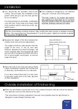
Measure the length of the hole between the
outside brick face and inner plasterwork.
The length should be 4mm greater than the
length of the hole ‘X’ but no less than
254mm, otherwise the Heat Exchanger will
not fit. Carefully mark the outer tube all round
and cut with a hacksaw and finish off with a
file or good quality sand paper, to remove
steps and swarf.
f)
Place the tube in the hole and ensure that it
slopes downwards towards the outside wall
to allow any condensation to run outwards.
If you have not achieved this you may have
to pack the inside end of the tube upwards
on final installation.
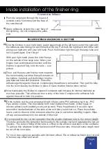
Outside installation of finisher ring
g)
Place the split finisher around the hole in the outside brickwork with the split at the bottom.
Use adhesive to secure the finisher to the wall.
This is best done from the outside but if access is not possible then the split finisher is
designed to pass through the large tube.
INNER WALL
OUTER WALL
SLOPED TO OUTSIDE


