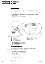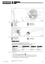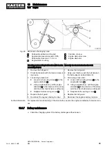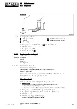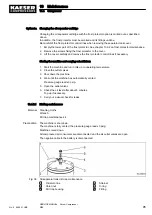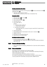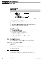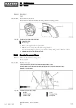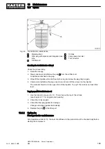
6. Replace the plug in the filler port.
7. Reconnect the negative battery terminal.
Starting the machine and carrying out a trial run
1. Start the machine and run in idle up to operating temperature.
2. Close the outlet valves.
3. Shut down the machine.
4. Wait until the machine has automatically vented.
Pressure gauge reads 0 psig.
5. Open the outlet valves.
6. Check the oil level after about 5 minutes.
Top up if necessary.
7. Carry out a visual check for leaks.
10.4.3 Changing the cooling oil
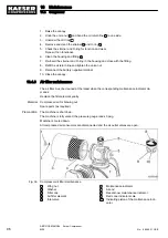
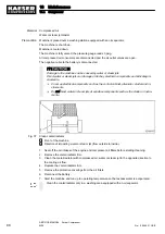
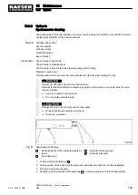
Drain all cooling-oil from:
■ Oil separator tank
■ Oil cooler
■ Oil pipes
Material See chapter 2.5.6 for oil filling volume.
Receptacle
New gasket for the drain plug
Funnel
Cleaning cloths
Precondition The machine is shut down.
The machine is standing level.
The machine is fully vented, the pressure gauge reads 0 psig.
The machine is at operating temperature.
All compressed air consumers are disconnected and the air outlet valves are open.
The negative cable to the battery is disconnected.
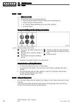
There is risk of burns from hot components and escaping oil.
➤ Wear long-sleeved clothing and gloves.
10 Maintenance
10.4 Compressor
90
SERVICE MANUAL Screw Compressor
M26
No.: 9_9446 01 USE
Summary of Contents for M26
Page 1: ...SERVICE MANUAL Screw Compressor M26 No 9_9446 01 USE...
Page 191: ...13 Annex 13 3 Dimensional drawing No 9_9446 01 USE SERVICE MANUAL Screw Compressor M26 183...
Page 193: ...13 Annex 13 3 Dimensional drawing No 9_9446 01 USE SERVICE MANUAL Screw Compressor M26 185...
Page 194: ...13 Annex 13 4 Electrical Diagram No 9_9446 01 USE SERVICE MANUAL Screw Compressor M26 187...
Page 195: ...13 Annex 13 4 Electrical Diagram 188 SERVICE MANUAL Screw Compressor M26 No 9_9446 01 USE...
Page 196: ...13 Annex 13 4 Electrical Diagram No 9_9446 01 USE SERVICE MANUAL Screw Compressor M26 189...
Page 197: ...13 Annex 13 4 Electrical Diagram 190 SERVICE MANUAL Screw Compressor M26 No 9_9446 01 USE...
Page 198: ...13 Annex 13 4 Electrical Diagram No 9_9446 01 USE SERVICE MANUAL Screw Compressor M26 191...
Page 199: ...13 Annex 13 4 Electrical Diagram 192 SERVICE MANUAL Screw Compressor M26 No 9_9446 01 USE...
Page 200: ...13 Annex 13 4 Electrical Diagram No 9_9446 01 USE SERVICE MANUAL Screw Compressor M26 193...
Page 201: ...13 Annex 13 4 Electrical Diagram 194 SERVICE MANUAL Screw Compressor M26 No 9_9446 01 USE...

