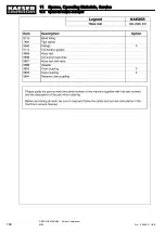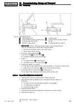
Fig. 44 Ball coupling function
1
Ball coupling (open)
2
Locking indicator (showing coupling open)
3
Coupling release lever (open)
4
Ball hitch (towing vehicle)
5
Coupling closed
6
Locking indicator (showing coupling
closed)
7
Coupling release lever (closed)
1.
There is considerable danger of injury caused by trapped fingers.
They can be trapped in the spring-loaded closing mechanism.
➤ Never place your fingers inside an open ball coupling.
➤ Always wear protective gloves.
2. Pull up the coupling release lever
3
.
3. Lower the coupling
1
onto the ball hitch
4
.
The coupling mechanism closes automatically.
4. Check if:
■ The locking indicator
6
is showing green.
■ The release lever is in the closed position
7
.
5. If the locking indicator is not visible:
■ Press down on the coupling until the closing mechanism can be heard to lock into place.
■ Press down on the release lever
7
to bring it to the horizontal position.
6. Check again that the locking indicator
6
is showing green.
The coupling is locked closed when the locking indicator shows green.
Carry out the following before starting to tow
1. Check that the coupling is properly latched onto the towing hitch.
2. Check that the towbar is adjusted to the correct height. See also chapter 6.3.
Check that:
■ The teeth in the tow bar height adjusting joints are fully engaged
■ The locking levers are tightened
■ The split pin is fully inserted.
3. Wind the propstand full up.
4. Check that the wheels are securely fitted and the tiyres are in good condition.
5. Check the tire pressures.
12 Decommissioning, Storage and Transport
12.2 Transporting
No.: 9_9446 01 USE
SERVICE MANUAL Screw Compressor
M26
169
Option sa
Summary of Contents for M26
Page 1: ...SERVICE MANUAL Screw Compressor M26 No 9_9446 01 USE...
Page 191: ...13 Annex 13 3 Dimensional drawing No 9_9446 01 USE SERVICE MANUAL Screw Compressor M26 183...
Page 193: ...13 Annex 13 3 Dimensional drawing No 9_9446 01 USE SERVICE MANUAL Screw Compressor M26 185...
Page 194: ...13 Annex 13 4 Electrical Diagram No 9_9446 01 USE SERVICE MANUAL Screw Compressor M26 187...
Page 195: ...13 Annex 13 4 Electrical Diagram 188 SERVICE MANUAL Screw Compressor M26 No 9_9446 01 USE...
Page 196: ...13 Annex 13 4 Electrical Diagram No 9_9446 01 USE SERVICE MANUAL Screw Compressor M26 189...
Page 197: ...13 Annex 13 4 Electrical Diagram 190 SERVICE MANUAL Screw Compressor M26 No 9_9446 01 USE...
Page 198: ...13 Annex 13 4 Electrical Diagram No 9_9446 01 USE SERVICE MANUAL Screw Compressor M26 191...
Page 199: ...13 Annex 13 4 Electrical Diagram 192 SERVICE MANUAL Screw Compressor M26 No 9_9446 01 USE...
Page 200: ...13 Annex 13 4 Electrical Diagram No 9_9446 01 USE SERVICE MANUAL Screw Compressor M26 193...
Page 201: ...13 Annex 13 4 Electrical Diagram 194 SERVICE MANUAL Screw Compressor M26 No 9_9446 01 USE...


