Material Compressed Air
Water or steam jet blaster
Precondition Machine is placed over a washing station equipped with an oil separator.
The machine is shut down.
Machine is cooled down.
The machine is fully vented, the pressure gauge reads 0 psig.
All compressed air consumers are disconnected and the air outlet valves are open.
The negative cable to the battery is disconnected.
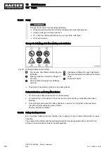
Damage to the machine can be caused by water or steam jets.
Direct water or steam jets can damage or destroy electrical components and indicating in‐
struments.
➤ Cover up electrical components such as the control cabinet, alternator, starter and in‐
struments.
➤ Do not direct water or steam jets at sensitive components such as the starter or instru‐
ments.
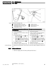
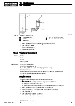
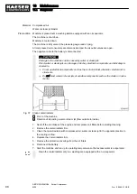
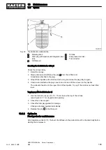
Fig. 37 Clean cooler/radiator
1
Front of the machine
2
Direction of impacting water or steam jet (from outside to inside).
1. Seal off the air intakes of the engine and compressor air filters before starting cleaning.
2. Remove the cooler/radiator trim.
3. Clean the cooler/radiator with compressed air, water or steam jet in the opposite direction to
the cooling air flow.
4. Replace the cooler/radiator trim.
5. Remove the protective coverings from the air filters.
6. Reconnect the battery.
7. Start the machine and run up to operating temperature so that excess water is evaporated.
Clean the cooler/radiator only in a washing area equipped with an oil separator.
10 Maintenance
10.4 Compressor
98
SERVICE MANUAL Screw Compressor
M26
No.: 9_9446 01 USE
Summary of Contents for M26
Page 1: ...SERVICE MANUAL Screw Compressor M26 No 9_9446 01 USE...
Page 191: ...13 Annex 13 3 Dimensional drawing No 9_9446 01 USE SERVICE MANUAL Screw Compressor M26 183...
Page 193: ...13 Annex 13 3 Dimensional drawing No 9_9446 01 USE SERVICE MANUAL Screw Compressor M26 185...
Page 194: ...13 Annex 13 4 Electrical Diagram No 9_9446 01 USE SERVICE MANUAL Screw Compressor M26 187...
Page 195: ...13 Annex 13 4 Electrical Diagram 188 SERVICE MANUAL Screw Compressor M26 No 9_9446 01 USE...
Page 196: ...13 Annex 13 4 Electrical Diagram No 9_9446 01 USE SERVICE MANUAL Screw Compressor M26 189...
Page 197: ...13 Annex 13 4 Electrical Diagram 190 SERVICE MANUAL Screw Compressor M26 No 9_9446 01 USE...
Page 198: ...13 Annex 13 4 Electrical Diagram No 9_9446 01 USE SERVICE MANUAL Screw Compressor M26 191...
Page 199: ...13 Annex 13 4 Electrical Diagram 192 SERVICE MANUAL Screw Compressor M26 No 9_9446 01 USE...
Page 200: ...13 Annex 13 4 Electrical Diagram No 9_9446 01 USE SERVICE MANUAL Screw Compressor M26 193...
Page 201: ...13 Annex 13 4 Electrical Diagram 194 SERVICE MANUAL Screw Compressor M26 No 9_9446 01 USE...

