29
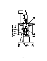
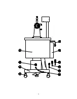
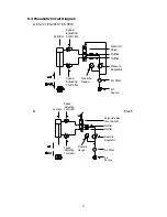
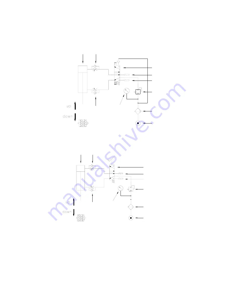
6.3 Pneumatic Circuit Diagram
A. KS-72 / KS-2010 / KS-3010
B. KS-85
Cylinder
Speed
Adjusting
Controller
Speed
Adjusting
Controller
Air Filter
Pressure
Regulator
Muffler
Muffler
Solenoid
Valve
Air
Source
Pressure
Gauge
Air Filter
Pressure
Regulator
Muffler
Muffler
Solenoid Valve
(Foot Switch)
Air
Source
Cylinder
Speed
Adjusting
Controller
Speed
Adjusting
Controller
Pressure
Gauge
Summary of Contents for KS-72
Page 12: ...11...
Page 13: ...12...
Page 22: ...21...
Page 23: ...22...
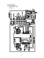
Page 31: ...30 6 4 Wiring Diagram A MAIN WIRING DIAGRAM A 1 KS 72...
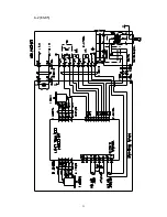
Page 32: ...31 A 2 KS 85...
Page 38: ...37 FUSE FUSE B GENERATOR CIRCUIT DIAGRAM KS 72 KS 85 KS 2010 KS 3010...


