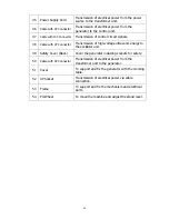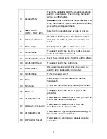
23
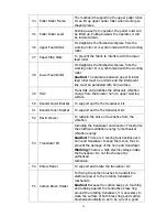
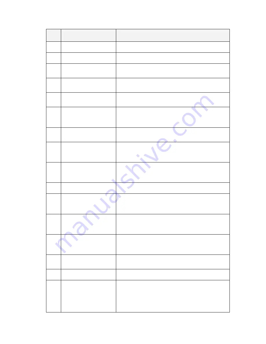
Item
Parts Name
Function Description
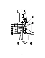
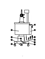
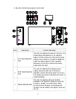
1
Generator
Converts power source into ultrasonic energy.
2
Working Table
Provide a workbench.
3 Spacer
To raise up the machine head’s height to increase
the convenience of pulling the fabric.
4 Machine
Head
Load the transmission gear, cylinder and rollers
etc.
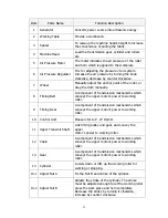
5
Air Pressure Meter
The meter indicates the air pressure of the roller
and horn which is applied to the workpiece.
6
Air Pressure Regulator
It is for adjusting the pressure of air system.
Increase the air pressure by turning the knob
clockwise, decrease by counter clockwise.
7 Wheel
Manually adjust the anchor point of the roller, or
drag the cloth manually.
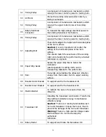
8 Timing
Belt
A component of transmission mechanisms which
conveys the upper motor’s power to working
roller.
9 Timing
Gear
A component of transmission mechanisms which
conveys the upper motor’s power to working
roller.
10 Control Unit
Please refer to
P. 27
Item D.
11 Upper Transmit Shaft
Link timing pulley and gear, and convey the
upper
motor’s power to working roller.
12 Chain
A component of transmission mechanisms which
conveys the upper motor’s power to working
roller.
13 Gear
A component of transmission mechanisms which
conveys the upper motor’s power to working
roller.
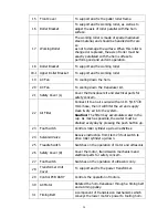
14 Cylinder
Lowers down or lifts up the working roller for
working or stopping.
14-1 Adjust Nut A
Fix the Nut B and stroke of the cylinder.
14-2 Adjust Nut B
Adjusts the stroke of the cylinder. The stroke
must be adjusted enough to let the working roller
press the work piece and horn completely.
Decrease the stroke by turning it clockwise,
increase by counter clockwise.
Summary of Contents for KS-72
Page 12: ...11...
Page 13: ...12...
Page 22: ...21...
Page 23: ...22...
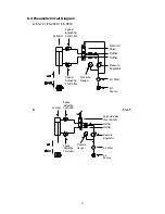
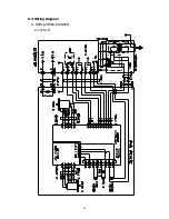
Page 31: ...30 6 4 Wiring Diagram A MAIN WIRING DIAGRAM A 1 KS 72...
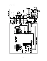
Page 32: ...31 A 2 KS 85...
Page 38: ...37 FUSE FUSE B GENERATOR CIRCUIT DIAGRAM KS 72 KS 85 KS 2010 KS 3010...


