15
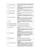
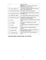
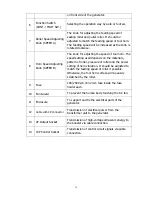
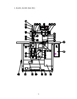
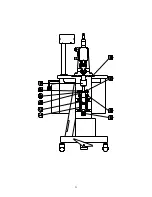
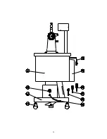
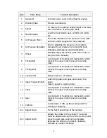
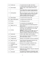
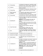
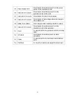
32 Belt Tension Bar
Adjust tension of the timing belt.
33 Lower Transmit Shaft
Link timing pulley to drive lower feed roller.
34 Conductive Brass Ring A Brass ring for electric conduction.
35 Timing
Pulley
A component of transmission mechanisms which
conveys the lower motor’s power to tooling horn.
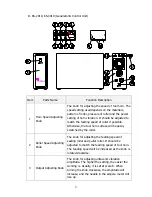
36 Adjusting
Bolt
These bolts adjust the height and horizontal plane
of the horn surface.
Caution:
It is very important not to alter the
setting of the horizontal plane of the horn
surface.
This should match the exact axis of the working
roller and should only be performed by a trained
technician or engineer.
37 Paper
Tape
It supplies the paper strip especially in cutting
cloth. Usually the paper strip must fit under the
workpiece and prevent direct contact between the
running horn and cutting roller, and helps to
prevent scratches on the horn surface. Also, it
prevents the melting materials from sticking on
the horn surface. And most importantly, when
cutting cloth, it acts as a cushion to the horn
surface and makes cutting cloth easier.
38 Paper Tension Bar
This is the mechanism which applies tension to
the paper strip and keeps it straight while paper
tape is passing through the working roller then to
the puller roller.
39 Paper Strip Guide
Guides the paper strip that is below the
workpiece
(used especially in cutting cloth) and in
transporting material to the puller roller.
40 O.P.P. Tape Guide
Used to guide the O.P.P. strip into the working
positions.
41 O.P.P.
Tape
The O.P.P. tape is used on top of the workpiece
and as well as helping in the transportation of the
material through the machine, makes the removal
of cuttings from the material much easier and
cleaner.
42 Pressure Adjusting Bolt
The setting of pressure depends on whether the
workpiece is carried out smoothly or not. On
some materials it may prevent creases if
tightened.
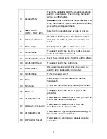
43 Fixed
Nut
It is for locking the pressure adjusting bolt to
prevent the bolt from moving while working.
Summary of Contents for KS-72
Page 12: ...11...
Page 13: ...12...
Page 22: ...21...
Page 23: ...22...
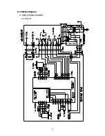
Page 31: ...30 6 4 Wiring Diagram A MAIN WIRING DIAGRAM A 1 KS 72...
Page 32: ...31 A 2 KS 85...
Page 38: ...37 FUSE FUSE B GENERATOR CIRCUIT DIAGRAM KS 72 KS 85 KS 2010 KS 3010...


