background image

3-10(No.XA008)

Servo control board

Block No. [0][2]

Symbol No.

Part No.

Part Name

Description

Local

IC101

AN8703FH-V

IC

Frontend processor for DVD

IC201

BA5983FM-X

IC

4-channel driver

IC251

BA6664FM-X

IC

Motor driver

IC301

MN103S26EDC-H IC

IC301

or MN103S26EGB-H IC

Super optical disc controller

IC402

AK4381VT-X

IC

2ch DAC

IC403

MN101C28DMJ

IC

IC404

BR93L46F-W-X

IC

IC405

SST39VF160H0973 IC

IC406

74LCX373MTC-X IC(DIGITAL)

Octal D-type latch

IC406

or 74LVC373APW-X IC(DIGITAL)

Octal D-type transparet latch

IC407

74LCX373MTC-X IC(DIGITAL)

Octal D-type latch

IC407

or 74LVC373APW-X IC(DIGITAL)

Octal D-type transparet latch

IC501

NDV8601VWA-BE IC

DVD on a chip processor

IC505

K4S643232F-TC60 IC

IC505

or HY57643220CT7 IC

IC505

or HY57643220CT55 IC

IC505

or K4S643232F-TC70 IC

IC505

or W986432DH-7

IC

Bits SDRAM

IC511

LM1117MP1.8-X

IC

Regulator

Q101

KTA1001/Y/-X

TRANSISTOR

Q101

or 2SB1424/R/-W

TRANSISTOR

Q102

KTA1001/Y/-X

TRANSISTOR

Q102

or 2SB1424/R/-W

TRANSISTOR

Q103

DTA144EE-X

DIGI TRANSISTOR

D101

RB521S-30-X

SB DIODE

D301

RB521S-30-X

SB DIODE

C105

NEA70JM-476X

E CAPACITOR

47uF 6.3V M

C106

NEA70JM-476X

E CAPACITOR

47uF 6.3V M

C109

NCB31CK-104X

C CAPACITOR

0.1uF 16V K

C110

NCS31HJ-221X

C CAPACITOR

220pF 50V J

C111

NCF31CZ-104X

C CAPACITOR

0.1uF 16V Z

C112

NCF31CZ-104X

C CAPACITOR

0.1uF 16V Z

C116

NCB31CK-104X

C CAPACITOR

0.1uF 16V K

C117

NCB31CK-473X

C CAPACITOR

0.047uF 16V K

C118

NCB31CK-273X

C CAPACITOR

0.027uF 16V K

C119

NCB31HK-561X

C CAPACITOR

560pF 50V K

C120

NCB31HK-561X

C CAPACITOR

560pF 50V K

C121

NCB31CK-104X

C CAPACITOR

0.1uF 16V K

C122

NCS31HJ-120X

C CAPACITOR

12pF 50V J

C123

NCF31CZ-104X

C CAPACITOR

0.1uF 16V Z

C124

NCS31HJ-470X

C CAPACITOR

47pF 50V J

C125

NCB31HK-271X

C CAPACITOR

270pF 50V K

C126

NCF31CZ-104X

C CAPACITOR

0.1uF 16V Z

C127

NCF31CZ-104X

C CAPACITOR

0.1uF 16V Z

C128

NCF31CZ-104X

C CAPACITOR

0.1uF 16V Z

C129

NCB31HK-472X

C CAPACITOR

4700pF 50V K

C135

NEA70JM-476X

E CAPACITOR

47uF 6.3V M

C137

NEA70GM-476X E CAPACITOR

47uF 4V M

C138

NCF31CZ-104X

C CAPACITOR

0.1uF 16V Z

C141

NCF31CZ-104X

C CAPACITOR

0.1uF 16V Z

C142

NCF31CZ-104X

C CAPACITOR

0.1uF 16V Z

C144

NCB31CK-103X

C CAPACITOR

0.01uF 16V K

C204

NCF31CZ-104X

C CAPACITOR

0.1uF 16V Z

C205

NCS31HJ-121X

C CAPACITOR

120pF 50V J

C207

NCB31HK-391X

C CAPACITOR

390pF 50V K

C208

NCB31HK-391X

C CAPACITOR

390pF 50V K

C211

NCB31HK-223X

C CAPACITOR

0.022uF 50V K

C212

NCB31CK-103X

C CAPACITOR

0.01uF 16V K

C217

NCF31CZ-104X

C CAPACITOR

0.1uF 16V Z

C251

NCF31CZ-104X

C CAPACITOR

0.1uF 16V Z

C253

NCF31CZ-104X

C CAPACITOR

0.1uF 16V Z

C255

NCB31CK-153X

C CAPACITOR

0.015uF 16V K

C256

NCB31CK-104X

C CAPACITOR

0.1uF 16V K

C257

NCF31CZ-104X

C CAPACITOR

0.1uF 16V Z

C258

NCF31CZ-104X

C CAPACITOR

0.1uF 16V Z

C259

NCF31CZ-104X

C CAPACITOR

0.1uF 16V Z

C260

NCF31CZ-104X

C CAPACITOR

0.1uF 16V Z

C261

NCF31CZ-104X

C CAPACITOR

0.1uF 16V Z

C262

NCF31CZ-104X

C CAPACITOR

0.1uF 16V Z

C263

NCF31CZ-104X

C CAPACITOR

0.1uF 16V Z

C264

NCB31CK-103X

C CAPACITOR

0.01uF 16V K

C301

NCF31CZ-104X

C CAPACITOR

0.1uF 16V Z

C302

NCF31CZ-104X

C CAPACITOR

0.1uF 16V Z

C303

NCF31CZ-104X

C CAPACITOR

0.1uF 16V Z

C304

NEA70GM-476X E CAPACITOR

47uF 4V M

C306

NEA70GM-476X E CAPACITOR

47uF 4V M

C308

NEA70GM-476X E CAPACITOR

47uF 4V M

C310

NCF31CZ-104X

C CAPACITOR

0.1uF 16V Z

C311

NCB31HK-561X

C CAPACITOR

560pF 50V K

C312

NCB31HK-561X

C CAPACITOR

560pF 50V K

C313

NCB31HK-561X

C CAPACITOR

560pF 50V K

C314

NCB31HK-331X

C CAPACITOR

330pF 50V K

C315

NCB31HK-471X

C CAPACITOR

470pF 50V K

C316

NCB31HK-271X

C CAPACITOR

270pF 50V K

C317

NCS31HJ-121X

C CAPACITOR

120pF 50V J

C318

NCF31CZ-104X

C CAPACITOR

0.1uF 16V Z

C319

NCB31HK-102X

C CAPACITOR

1000pF 50V K

C320

NCB31HK-102X

C CAPACITOR

1000pF 50V K

C321

NCB31HK-102X

C CAPACITOR

1000pF 50V K

C322

NCB31HK-562X

C CAPACITOR

5600pF 50V K

C323

NCB31HK-102X

C CAPACITOR

1000pF 50V K

C324

NCF31CZ-104X

C CAPACITOR

0.1uF 16V Z

C325

NCS31HJ-470X

C CAPACITOR

47pF 50V J

C326

NCB31CK-183X

C CAPACITOR

0.018uF 16V K

C327

NCB31HK-102X

C CAPACITOR

1000pF 50V K

C328

NCF31CZ-104X

C CAPACITOR

0.1uF 16V Z

C329

NCB31CK-103X

C CAPACITOR

0.01uF 16V K

C330

NCB31CK-104X

C CAPACITOR

0.1uF 16V K

C331

NCB31CK-103X

C CAPACITOR

0.01uF 16V K

C332

NCF31CZ-104X

C CAPACITOR

0.1uF 16V Z

C333

NCB31CK-104X

C CAPACITOR

0.1uF 16V K

C334

NCB31CK-104X

C CAPACITOR

0.1uF 16V K

C337

NCF31CZ-104X

C CAPACITOR

0.1uF 16V Z

C338

NCF31CZ-104X

C CAPACITOR

0.1uF 16V Z

C339

NCB31CK-104X

C CAPACITOR

0.1uF 16V K

C340

NCB31CK-104X

C CAPACITOR

0.1uF 16V K

C341

NCF31CZ-104X

C CAPACITOR

0.1uF 16V Z

C342

NCB31HK-471X

C CAPACITOR

470pF 50V K

C343

NCF31CZ-104X

C CAPACITOR

0.1uF 16V Z

C344

NCB31HK-471X

C CAPACITOR

470pF 50V K

C345

NCF31CZ-104X

C CAPACITOR

0.1uF 16V Z

C346

NCF31CZ-104X

C CAPACITOR

0.1uF 16V Z

C347

NCF31CZ-104X

C CAPACITOR

0.1uF 16V Z

C348

NCB31CK-104X

C CAPACITOR

0.1uF 16V K

C349

NCF31CZ-104X

C CAPACITOR

0.1uF 16V Z

C350

NCF31CZ-104X

C CAPACITOR

0.1uF 16V Z

C351

NCB31HK-471X

C CAPACITOR

470pF 50V K

C360

NEA70GM-476X E CAPACITOR

47uF 4V M

C407

NCF31CZ-104X

C CAPACITOR

0.1uF 16V Z

C408

NEA70JM-227X

E CAPACITOR

220uF 6.3V M

C409

NEA70JM-227X

E CAPACITOR

220uF 6.3V M

C410

NCF31CZ-104X

C CAPACITOR

0.1uF 16V Z

C411

NCB31CK-104X

C CAPACITOR

0.1uF 16V K

C412

NCF31CZ-104X

C CAPACITOR

0.1uF 16V Z

C413

NCF31CZ-104X

C CAPACITOR

0.1uF 16V Z

C414

NCF31CZ-104X

C CAPACITOR

0.1uF 16V Z

C415

NCF31CZ-104X

C CAPACITOR

0.1uF 16V Z

C416

NCF31CZ-104X

C CAPACITOR

0.1uF 16V Z

C417

NCF31CZ-104X

C CAPACITOR

0.1uF 16V Z

C418

NCF31CZ-104X

C CAPACITOR

0.1uF 16V Z

C419

NCF31CZ-104X

C CAPACITOR

0.1uF 16V Z

C421

NCF31CZ-104X

C CAPACITOR

0.1uF 16V Z

C422

NCF31CZ-104X

C CAPACITOR

0.1uF 16V Z

C423

NCF31CZ-104X

C CAPACITOR

0.1uF 16V Z

C424

NCB31CK-103X

C CAPACITOR

0.01uF 16V K

C432

NCB31CK-223X

C CAPACITOR

0.022uF 16V K

C440

NDC31HJ-101X

C CAPACITOR

100pF 50V J

C501

NCF31CZ-104X

C CAPACITOR

0.1uF 16V Z

C506

NDC31HJ-150X

C CAPACITOR

15pF 50V J

C507

NDC31HJ-180X

C CAPACITOR

18pF 50V J

C510

NCB31HK-471X

C CAPACITOR

470pF 50V K

C512

NCF31CZ-104X

C CAPACITOR

0.1uF 16V Z

C513

NCB31HK-471X

C CAPACITOR

470pF 50V K

C514

NCB31HK-471X

C CAPACITOR

470pF 50V K

C515

NCB31HK-471X

C CAPACITOR

470pF 50V K

C516

NCB31HK-471X

C CAPACITOR

470pF 50V K

C517

NCF31CZ-104X

C CAPACITOR

0.1uF 16V Z

C518

NCF31CZ-104X

C CAPACITOR

0.1uF 16V Z

Symbol No.

Part No.

Part Name

Description

Local

Summary of Contents for XV-M5GSL

Page 1: ...4 ADJUSTMENT 1 20 5 TROUBLE SHOOTING 1 26 Area Suffix J U S A C Canada 2 5 8 1 4 7 3 6 9 0 10 10 TITLE GROUP TV VIDEO CANCEL RETURN VOL VOL CH CH VFP ZOOM AMP VOL AUDIO 3D PHONIC SUBTITLE ANGLE DIMMER REPEAT OPEN CLOSE DISC SELECT TV1 TV2 TV3 TV4 TV5 TV6 TV7 TV8 TV9 TV TV0 MUTING TV DVD NEXT PREVIOUS SELECT CLEAR SLOW SLOW T OP MENU MENU ON SCREE N CHOICE ENTER STANDBY ON TV DVD PROGRESSIVE SCAN V...

Page 2: ...5 ohm C Output 286 mVp p 75 ohm Horizontal resolution 500 lines or more ANALOG OUT pin jack 2 0 Vrms 10 kohm DIGITAL OUT COAXIAL 0 5 Vp p 75 ohm termination DIGITAL OUT OPTICAL 21 dBm to 15 dBm peak Frequency response CD sampling frequency 44 1 kHz 2 Hz to 20 kHz DVD sampling frequency 48 kHz 2 Hz to 22 kHz 4 Hz to 20 kHz for DTS and Dolby Digital bitstream signals DVD sampling frequency 96 kHz 2 ...

Page 3: ...arts of the product an tenna terminals knobs metal cabinet screw heads headphone jack control shafts etc to be sure the product is safe to operate without danger of electrical shock Do not use a line isolation transformer during this check Plug the AC line cord directly into the AC outlet Using a Leakage Current Tester measure the leakage current from each exposed metal parts of the cabinet partic...

Page 4: ...ckup In order to maintain quality during transport and before installation both sides of the laser diode on the replacement optical pickup are shorted After replacement return the shorted parts to their original condition Refer to the text Do not use a tester to check the condition of the laser diode in the optical pickup The tester s internal power source can easily destroy the laser diode 1 6 Ha...

Page 5: ...B917 B923 B926 B927 B925 B924 R901 R903 R906 R910 R912 R913 R915 R951 R954 T901 EP910 D904 B903 B904 B905 Full Fuse Replacement Marking Graphic symbol mark This symbol means fast blow type fuse should be read as follows FUSE CAUTION FOR CONTINUED PROTECTION AGAINST RISK OF FIRE REPLACE ONLY WITH SAME TYPE AND RATING OF FUSES F901 1 6 A 125 V F901 1 6 A 125 V Marquage Pour Le Remplacement Complet D...

Page 6: ...tical block Do not change the setting of these half fixed resistors for laser power adjustment 1 8 2 Destruction of Traverse Unit and Laser Pickup by Static Electricity Laser diodes are easily destroyed by static electricity charged on clothingor the human body Before repairing peripheral elements of the traverse unit or pickup be sure to take the following electrostatic protection 1 Wear an antis...

Page 7: ... No XA008 1 7 SECTION 2 SPECIFIC SERVICE INSTRUCTIONS This service manual does not describe SPECIFIC SERVICE INSTRUCTIONS ...

Page 8: ...isconnect the card wire from connector CN501 CN702 on the servo control board and signal output terminal board respectively 3 Remove the three screws C attaching the front panel as sembly on the bottom of the main body 4 Hook a and b are removed respectively and the front panel assembly is removed 3 1 3 Removing the changer mechanism assembly See Figure 2 Figure 4 Prior to performing the following...

Page 9: ...ower supply board 2 Disconnect the socket wire from connector P901 on the power supply board 3 Remove the three screws F attaching the power supply board 4 Remove the one screw G attaching the power supply board on the back of the main body 3 1 6 Removing the signal output terminal board See Figure 6 Figure 7 Prior to performing the following procedure remove the top cover 1 Disconnect the card wi...

Page 10: ...of the body to unlock the tray assembly Draw out the trays to ward the front Attention The tray can be locked if all tray assemblies are at tached 5 From top of the body move the stopper tab c in the direc tion of the arrow and release Pull out the tray assemblies from the body Caution Remove the tray assembly from top tray 5 in order Attention When reattaching the sub tray of the tray assembly or...

Page 11: ...d disconnect connector CN2 on the motor board 4 Disconnect the card wire from connector CN1 on the motor board Caution When reconnecting the card wire let the card wire through the slot d of the motor board and attach it to the bottom of the body using a double tape Fig 6 3 2 3 Removing the traverse mechanism assembly See Fig 7 Prior to performing the following procedure remove the servo control b...

Page 12: ...on of the arrow The guide collar is also removed Be sure to solder the short round point f on the pickup be fore removing the flexible wire from the pickup In assem bling procedure connect the flexible wire to the connector and then be sure to unsolder the short round point Insert the guide collar in the worm shaft before attaching the pickup 3 Remove the two screws E attaching the rack plate and ...

Page 13: ...ide of the body remove the spacer fixing the tray switch board and motor board Disconnect connector CN3 on the tray switch board and detach the side L upward 3 Remove the screw G attaching the tray switch board 4 Push the joint tab g of the side L in the direction of the ar row and remove the tray switch board outward then re lease joint h Fig 9 Fig 10 Fig 11 F F Side L CN3 Spacer Side L F F g h G...

Page 14: ...d to part k of the hook on the right side of the body 5 From top of the body turn the gear 1 clockwise to move the elevator cam rearward Move the two slots l and joint m of the elevator cam as shown in Fig 16 and remove the ele vator cam outward 6 Remove the three screws I and detach the side R upward Caution When reattaching the side R assembly make sure to fit the shaft part n into the slot of t...

Page 15: ... tab o of the hook stopper to unlock it Release four joints p to detach from the rack holder Release the rod from part q 4 Turn the gear 1 clockwise again to move the lifter assembly upward 5 Remove the lifter assembly from the body upward at posi tion r where the four pins on the right and left sides of the lifter assembly fit to the notches of the s Move the lifter assembly toward the front and ...

Page 16: ...ove the spring attached to the bottom of the sensor as sembly from the boss w on the sensor slider 5 Remove the screw L and M attaching the sensor board and SV resister respectively If necessary unsolder the sensor board Caution When reattaching the SV resister attach the sensor slider to the sensor bracket and fit the lever on the bottom of the SV re sister into slot x of the sensor slider Cautio...

Page 17: ...g 25 Fig 26 Fig 27 Fig 28 K K w u v Spring Sensor assembly Spring Sensor slider x z w L M x Soldering point Sensor board SV resister Sensor braket Sensor slider y z w v K Sensor assembly Slide gear Spring Slide lever K ...

Page 18: ...ove the two belts on top of the body 2 Remove the four screws N attaching the motor 3 Remove the motor board from the bottom of the body Refer to the section Removing the motor board Attention When removing the motor board with the motor you need not to unsolder four soldered parts Caution When reattaching the motor turn the side where the label should be put to the front side Fig 29 Fig 30 Motor ...

Page 19: ...ward the front 4 From top of the body turn the gear 1 clockwise to move the lifter assembly upward 5 From top of the body turn the gear 2 clockwise to move the sub tray remaining inside the lifter assembly toward the front then pull out 6 Take out the DISC on the sub tray 7 After clearing away the DISC insert the sub tray into the main tray Caution When reattaching the sub tray move the tray stopp...

Page 20: ...onfirm the symptoms that a customer points out First Initialize and then confirm whether the symptoms are improved or not After servicing before returning the main body to a customer Initialized main body should be returned to a customer 1 Set the main body at test mode 2 Press PAUSE key of the main body 3 When initialization is completed the FL display changes from 0 to 00 The left 0 of 00 is not...

Page 21: ...ftware 3 Remove the disc when the FL display changes from READING to disc information 4 Perform the same procedures as in 2 and 3 above by using the test disc CTS 1000 or commercial CD DA software 5 Set the main body at test mode and check that the FL display shows 0 NOTE Status of this adjustment can be judged by the number displayed at test mode as follows NOTE As for a disc used for adjustment ...

Page 22: ...teriorated To return to test mode press STOP key of the main body 4 7 Flap adjustment of the pick up guide shaft Please perform flap adjustment of the pick up guide shaft in the following case Just after you exchange the pick up Just after you exchange the spindle motor Just after you exchange the traverse mechanism base NOTE Please perform flap adjustment of the pick up guide shaft when you excha...

Page 23: ...ess the numeric key 1 of the remote controller for automatic adjustment 4 After a few seconds press the numeric key 6 of the remote controller Then the FL display displays a jitter value 5 Turn the adjustment screws on the underside of the traverse mechanism with phillips screw driver until the maximum jitter value is displayed on the FL display In this model a bigger jitter value means a better r...

Page 24: ...ess POWER key of the main body When the stand by indicator is lighted upgrading is completed 7 Set the main body at test mode and perform initialization Then confirm the version of the firmware When up grade is completed Upgrade application initializing While upgrading blue screen After inserting the up grade disc Firmware upgrade Disc press UP NO DISC 2 5 8 1 4 7 3 6 9 0 10 10 TITLE GROUP TV VIDE...

Page 25: ...isplayed correctly FL Display should light correctly without any unevenness All Function button All function buttons should worked correctly with moderate click feeling Open and close movement of tray When press OPEN CLOSE button the tray should move smoothly without any noise Remote controller unit working Check the correctly operation in use of remote controller unit Reading of TOC Be not long i...

Page 26: ...inues for several seconds and becomes NO DISC or an error display afterwards The rotation of DISC becomes high speed and abnormal and becomes NO DISC or an error display afterwards Is focus retraction OK Even when it retracts correctly if it is out of focus and makes repeated retries with a clicking sound it is in error Is tracking retraction OK If TE waveform reappears or fails to converge after ...

Page 27: ...n of the motor 5 2 2 Disc Detection Distinction error no disc no RFENV Laser is defective Front End Processor is defective IC101 APC circuit is defective Q101 Q102 Pattern is defective Lines for CN101 All patterns which relate to pick up and patterns between IC101 IC101 For signal from IC101 to IC301 is signal output from IC101 20 ASOUT and IC101 41 RFENV and IC101 22 FEOUT 5 2 3 Traverse movement...

Page 28: ...traverse movement NG in Check points for each error when it is not normal Are not there caught of the feeding mech anism etc 5 2 10 Picture is distorted or abnormal sound occurs at intervals of several seconds Is the feed operation normal Are not there caught of the feeding mechanism etc 5 2 11 Others The image is sometimes blocked and the image stops The image is blocked when going to outer thoug...

Page 29: ... MEMO ...

Page 30: ... No XA008 AV MULTIMEDIA COMPANY OPTICAL DISC CATEGORY 1644 Shimotsuruma Yamato Kanagawa 242 8514 Japan VICTOR COMPANY OF JAPAN LIMITED WPC Printed in Japan ...

Page 31: ...tion column shows the number of the used part XV M5GSL Contents Exploded view of general assembly and parts list DVD Traverse mechanism assembly and parts list DVD Changer mechanism assembly and parts list Electrical parts list Packing materials and accessories parts list 3 2 3 4 3 6 3 8 3 13 Area Suffix J U S A C Canada ...

Page 32: ... c c Power Block No M1MM Signal output 39 38 39 Operation FL display board 10 10 13 11 14 15 15 9 8 12 5 6 switch board 2 3 1 4 17 18 supply board terminal board 20 34 19 22 23 24 21 24 25 27 33 30 31 32 29 28 27 26 35 16 BACK SIDE 36 40 44 43 42 41 16 SIDE BACK Power switch board ...

Page 33: ...ING SCREW SYSTEM CB x3 20 QYSBSGG3008E TAPPING SCREW PRIMARY CB x3 21 5DVD CHANGER ME 22 QUQA10 0715AJ FFC WIRE CN503 23 QUQ110 2322BJ FFC WIRE CN502 24 QYSBSG3008Z TAPPING SCREW MECHA CHASSIS x4 25 LE30001 031A SPACER x2 26 LE20715 001A REAR PANEL 27 QYSBSGY3008M SPECIAL SCREW REAR CHASSIS x3 28 QYSBSGY3008M SPECIAL SCREW COMPONENT x2 29 QYSBSGY3008M SPECIAL SCREW S VIDEO OUT 30 QYSBSGY3008M SPEC...

Page 34: ...echanism assembly and parts list Block No M2MM 0 2mm 1 7mm _ JVS 1003 Grease JVG 31N 4 30 30 1 12 13 3 9 26 19 22 23 21 20 11 28 27 32 31 10 24 18 17 7 8 16 15 31 2 14 6 5 31 32 9 25 32 32 31 30 33 29 a FXL D5 1M 7 7mm 0 2mm _ a ...

Page 35: ...FT HOLDER 13 QYSDST2008Z TAP SCREW FOR G S HOLDER 14 LV43291 002A GUIDE SHAFT 15 LV33991 001A ADJUST SPRING 16 QYSPST2008Z TAP SCREW FOR GS ADJ SP 17 QAL0478 001 PICK UP 18 LV33983 001A PS SPRING 19 QYSPSFT1730Z TAP SCREW FOR PS SPRING 20 LV33984 002A RACK ARM 21 QYSPSFT1730Z TAP SCREW FOR RACK ARM x2 22 LV33986 001A S SHAFT GEAR 23 LV43293 001A SCREW SHAFT 24 LV43290 001A S SHAFT COLLOR 25 LV3398...

Page 36: ... 47 48 29 31 30 32 32 10 10 45 44 36 16 21 9 37 8 8 37 33 26 25 24 39 28 28 23 27 28 14 13 4 3 12 17 17 17 7 40 15 41 22 5 6 42 1 11 DVD servo board 19 2 53 52 52 51 50 38 49 d G D C d B F c E D b G A a C B A E F i a b c Block No M3MM EMU SD2 1M JVG 31N JVS 1003 Grease 49 49 43 54 ...

Page 37: ...4 LV33975 001A GEAR COVER 25 LV33976 001A ELEVATOR CAM 26 LV43287 001A ELEVATOR SPRING 27 LV33977 002A CLICK SPRING 28 QYSDST2605Z SCREW SIDE R x3 29 QYSDSF2608Z SCREW 2 6mm x 8mm 30 LV10749 002A SIDE L 31 LV33980 001A OPEN DET LEVER 32 QYSDST2605Z SCREW SIDE L x2 33 LV10746 002A TRAY ASSY x5 34 LV10750 002A TOP COVER 35 LV43289 002A ROD x2 36 QYSDSF2608Z SCREW TOP COVER x2 37 QYSDST2605Z SCREW MO...

Page 38: ... C764 QETN1CM 107Z E CAPACITOR 100uF 16V M C765 QETN1CM 107Z E CAPACITOR 100uF 16V M C791 QETN1EM 475Z E CAPACITOR 4 7uF 25V M C792 NCS31HJ 331X C CAPACITOR 330pF 50V J C793 QETN0JM 107Z E CAPACITOR 100uF 6 3V M C794 NCB31CK 104X C CAPACITOR 0 1uF 16V K C795 QETN1EM 476Z E CAPACITOR 47uF 25V M C797 NCS31HJ 151X C CAPACITOR 150pF 50V J C798 NCB31CK 104X C CAPACITOR 0 1uF 16V K C803 QETN0JM 227Z E C...

Page 39: ... RESISTOR 10kΩ 1 4W J R915 QRE141J 103Y C RESISTOR 10kΩ 1 4W J R952 NRSA63J 103X MG RESISTOR 10kΩ 1 16W J R953 NRSA63J 103X MG RESISTOR 10kΩ 1 16W J R954 QRZ9005 100X FUSI RESISTOR 10Ω R955 NRSA63J 223X MG RESISTOR 22kΩ 1 16W J R956 NRSA63J 103X MG RESISTOR 10kΩ 1 16W J R960 NRSA63J 471X MG RESISTOR 470Ω 1 16W J R961 NRSA63J 103X MG RESISTOR 10kΩ 1 16W J R962 NRSA63F 392X MG RESISTOR 3 9kΩ 1 16W F...

Page 40: ...1uF 16V Z C303 NCF31CZ 104X C CAPACITOR 0 1uF 16V Z C304 NEA70GM 476X E CAPACITOR 47uF 4V M C306 NEA70GM 476X E CAPACITOR 47uF 4V M C308 NEA70GM 476X E CAPACITOR 47uF 4V M C310 NCF31CZ 104X C CAPACITOR 0 1uF 16V Z C311 NCB31HK 561X C CAPACITOR 560pF 50V K C312 NCB31HK 561X C CAPACITOR 560pF 50V K C313 NCB31HK 561X C CAPACITOR 560pF 50V K C314 NCB31HK 331X C CAPACITOR 330pF 50V K C315 NCB31HK 471X ...

Page 41: ...9 NRSA63J 223X MG RESISTOR 22kΩ 1 16W J Symbol No Part No Part Name Description Local R213 NRSA63J 103X MG RESISTOR 10kΩ 1 16W J R214 NRSA63J 103X MG RESISTOR 10kΩ 1 16W J R215 NRSA63J 103X MG RESISTOR 10kΩ 1 16W J R219 NRSA63J 183X MG RESISTOR 18kΩ 1 16W J R220 NRSA63J 243X MG RESISTOR 24kΩ 1 16W J R221 NRSA63J 682X MG RESISTOR 6 8kΩ 1 16W J R230 NRSA63J 332X MG RESISTOR 3 3kΩ 1 16W J R251 NRS125...

Page 42: ...007 002X FERRITE BEADS X301 NAX0566 001X C RESONATOR 16 934MHz X401 NAX0248 001X C OSCILLATOR X571 NAX0550 001X CRYSTAL 27 000MHz Symbol No Part No Part Name Description Local IC1 LB1641 IC DC Motor driver IC2 LB1641 IC DC Motor driver D1 MTZJ6 2A T2 Z DIODE C1 QEKC1AM 107Z E CAPACITOR 100uF 10V M C2 QCFB1HZ 104Y C CAPACITOR 0 1uF 50V Z C3 QFLC1HJ 103Z M CAPACITOR 0 01uF 50V J C5 QFLC1HJ 103Z M CA...

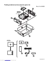
Page 43: ... No XA008 3 13 Packing materials and accessories parts list ACC SA A7 A6 A5 A4 A3 Important P4 FINAL ASSY ACC SA FRONT P2 P3 Block No M4MM A8 A2 A1 P5 P1 ...

Page 44: ...36 001A INST BOOK English Only ver J A 3 YU20333 SAFETY INST Only ver J A 4 BT 51028 2 J REGIST CARD Only ver J A 5 QAM0328 001 AV CORD 3P A 6 RM SXV050J REMOCON UNIT A 7 BATTERY x2 A 8 QPC02504015P POLY BAG FOR ACC INST P 1 QPC06005515P POLY BAG FOR SET P 2 LE31077 001A PACKING CASE P 3 LE20721 002A PACKING PAD L LEFT P 4 LE20722 002A PACKING PAD R RIGHT P 5 QPC01003015 ENVELOPE 10cm x 30cm ...

Page 45: ...grams 2 7 Printed circuit boards 2 15 Area Suffix J U S A C Canada 2 5 8 1 4 7 3 6 9 0 10 10 TITLE GROUP TV VIDEO CANCEL RETURN VOL VOL CH CH VFP ZOOM AMP VOL AUDIO 3D PHONIC SUBTITLE ANGLE DIMMER REPEAT OPEN CLOSE DISC SELECT TV1 TV2 TV3 TV4 TV5 TV6 TV7 TV8 TV9 TV TV0 MUTING TV DVD NEXT PREVIOUS SELECT CLEAR SLOW SLOW T OP MENU MENU ON SCREE N CHOICE ENTER STANDBY ON TV DVD PROGRESSIVE SCAN V I D...

Page 46: ...arts side of the PWB diagrams the parts that are printed over with black such as the resistor diode and ICP or identified by the mark nearby are critical for safety When replacing them be sure to use the parts of the same type and rating as specified by the manufacturer Except the JC version ...

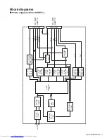
Page 47: ...8 C959 L952 AC DC D953 C952 C955 L951 AC DC D954 C967 C988 L955 AC DC D956 L953 C963 C965 AC DC D957 L954 C964 C966 FEED BACK PC901 AC DC D951 C950 FL ON OFF Q951 Q952 D5V REG IC951 3 3V REG Q953 TO FW801 SHEET 2 D5V M9V D3 3V TO FW651 SHEET 4 JT901 JT902 Block diagrams Power supply section SHEET 1 12V 12V F F VDISP B3 3V B3 3V JT903 JT904 D5V STANDBY ...

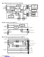
Page 48: ...9 S810 S811 S812 S813 S814 S815 S816 DISC1 5 LED D841 D842 D843 D844 D845 F F POWERON 1G 11G S1 S17 RESET KEYIN1 4 DISC1LED DISC5LED REMO OSC1 OSC2 CN871 CN805 Standby LED D851 Power switch S851 POWERSW STBYLED CN854 CN804 CN803 CN802 PROGRN PRORED Audio Video signal output terminal section SHEET 4 CN601 TO CN502 SHEET 7 TO SHEET 3 TO SHEET 3 COUT YOUT CbOUT SCOMP CrOUT SPDIF DOUTCNT AUDIO L R PRO...

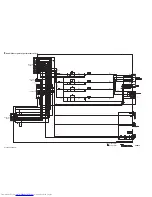
Page 49: ...EET 3 TO CN601 SHEET 4 FROM Pick up Unit FROM Spindle motor assembly FROM Loading motor assembly and tray detect Switch CN201 CN104 CN103 FM FM VH SM1 3 H1 H3 H1 H3 SPMUTE FG SPDRV SBRK DRVMUTE STEDSW AD0 15 PWE0 LA0 3 AD8 19 LADD4 19 TRVSW CN502 S3 3V D3 3V S5V B3 3V M5V M9V TO CN802 SHEET 2 AMUTE DA converter IC402 16 9MHz X301 LA0 LA3 AD0 AD3 OSC I1 O1 PCMCLK BCK AOUT0 LRCLK DACDENA DAC0CS SSPC...

Page 50: ...2 6 No XA008SCH MEMO ...

Page 51: ...63 R964 R965 C954 CP951 T901 R951 R913 C988 L955 FC901 R956 FC902 R955 B901 C918 QGD2501C1 05Z GND 0 001 AC250v QGD2501C1 03Z QGD2501C1 05Z QGD2501C1 04Z GND 68K 10K 3 3M 10 22 NI DI106 0 068 AC250V 2SD2264 R T QQR0816 001 QGA7901C1 02 47 400 1F4 T2 0 0033 1K 1F4 T2 1000 6 3 22K PC123Y22 MIP2C40MP 220 0 1 270K 470 1K NI 0 22 47P 1SS244 T2 TL431 A T 100 6 3 0 001 AC250V 22 35 470 10 100 10 1 0 NI 1...

Page 52: ...25MVW L T SLR 342MC T 4 7K 10K 430 430 430 680 680 120 1 1K 120 120 2 2K 120 120 2 2K KRC107S X QRB139J 104 10K QGF1205F1 07 220 6 3 10K MN101C35DLW 2 2K QAX0667 001Z KRC107S X 1u NI QGF1205F1 11 220 100K KRC102S X QGF1205F1 11 NI 100K 0 1 100K 330P KRC102S X KRC102S X KRC102S X KRC102S X 0 1 1K 0 01 2 2K 2 2K 2 2K 2 2K 82 120 100K 0 022 QGF1205F1 05 QGF1205F1 05 1K 1SS133 T2 KEYIN2 SCOMP KARAOKE ...

Page 53: ...7K 200 470p 0 0033 470p 100 16 2K 2 2K 200 NI 4 7K 2K 2 2K 200 4 7K 200 2 2K 2K 4 7K 0 0033 470p 470p 22 25 22 25 560 560 27K 27K 0 0022 0 0022 10K 0 0015 100K NI KRA102S X 100 100 2SC2412K RS X 10K NI 0R0 47K 47K NQR0227 004X 74VHCT08ASJ X 47 25 NI KRC109S X GP1FA352TZ 150P 100 6 3 10K 0 1 10 2SC3576 JVC T 300 QGF1205C1 07 HA17558AF X HA17558AF X 4 7 25 1M 10K 0R0 10K QNN0573 001 2SC3576 JVC T 1M...

Page 54: ...82 R883 C883 C651 C652 C653 NI 0 QNN0574 002 75 NI QND0111 001 QGD2501C1 04Z 1 50 75 QGF1016C1 23 82 82 68P 22P 1uH 1uH 1uH 1uH 330P 220P 22P NI 220P 22P 220P QUM15A 28DGZ4 NI 68P 68P 68P NI 150P QSW1033 001 NI NI NI NI 0 1 16 NI QNS0219 001 2 2 100 QSW1003 001 10 10 0 10 100P 10K NI NI 100 NI 220 6 3 220 6 3 220 6 3 VGND COMPULINK DGND SCOMP 12V 12V MICIN A5V INT_PROG_NTB AGND Lch Rch Rch Lch PRO...

Page 55: ...1 16 470P QGA2001F2 02X QGA2001F2 03X NI NQR0007 002X BA5983FM X BA6664FM X 0 1 16 QGF1037F1 15W NI M5V NI DGND 1 M9V NI MGND DGND MGND 10K 10K 10K 0 022 0 01 16 0 1 16 0 1 16 0 1 16 0 1 16 0 47 2 2 0 1 16 NI 0 1 16 M9V MGND DGND M5V 10K 0 015 16 0 1 16 47 47 47K 30K NI 120P 27K 27K 22K 22K 390P 390P 0 01 16 MN103S26EGB H SGND DGND DTA144EE X NAX0566 001X 1M 0 1 16 0 1 16 0 1 470P 0 1 16 4 7K 4 7K...

Page 56: ... 470P 0 1 16 470P 0 1 16 0 1 16 0 1 16 470P 470P 470P 0 1 16 47 4 47 4 NI NQR0007 002X NI 0 1 16 NI NI NI NI NI NI NI NI NI 470P 470P 470P 470P 470P 470P 470P 470P 470P NI 470P 10 NI NI 0 1 16 0 1 6K 1 6K NI NI 150 150 150 100 470 470P NI NI NQR0007 002X 0 1 16 NQR0007 002X NI 0 1 16 0 1 16 470P 0 1 16 0 1 16 470P 0 1 16 0 1 16 470P 0 1 16 PWE1 MD10 MD11 MD12 WE MD13 MD14 MD15 MCLK DQM1 MA9 MA8 MA...

Page 57: ...0 0 1 16 0 1 16 NI VGND VGND AGND NI NQR0129 002X NI NI NI NI NI NI NI 0 022 NI NI NI NI NI NI NI 0 022 DGND DGND DGND DGND AGND DGND SGND DGND FGND2 FGND1 FGND3 FGND4 10K 10K DGND DGND DGND 330 NI VGND DGND 10 1SS355 X 0 1 0 1 47 4 47 4 10K AD30 AD28 AD26 AD24 AD23 AD22 AD21 AD19 AD17 AD16 AD15 AD14 AD13 AD12 AD11 AD10 AD8 AD7 AD6 AD5 AD3 AD1 PWE0 LADD16 LA0 LA2 RD AD15 LHLD AD7 DAC0CS AD14 DAC2C...

Page 58: ...2 14 No XA008SCH NOTES VOLTAGES ARE DC MEASURED WITH A DIGITAL VOLT METER WITHOUT INPUT SIGNAL CONDITION POWER ON DVD STOP SHEET 8 Voltage value table ...

Page 59: ...4 C632 C633 C634 C640 C641 D601 D611 D621 D631 K621 K631 L601 L611 L612 L613 R621 R631 EP603 EP602 C743 C744 C745 R741 JT701 CN871 D841 D842 D843 D844 D845 Q841 Q842 Q843 Q844 Q845 R822 R823 R824 R825 R826 R827 R828 R829 R830 R831 R832 R841 R842 R843 R844 R845 S802 S803 S804 S805 S806 S807 S808 S809 S810 S811 S812 S813 S814 S815 S816 C801 C802 C803 C804 C805 C806 C807 C808 C811 C812 C884 CN802 CN8...

Page 60: ...9 TP510 TP511 TP512 TP513 TP514 TP515 TP516 TP517 518 TP519 520 521 TP522 TP523 TP524 TP525 TP526 TP527 TP528 TP529 TP530 TP531 TP532 TP533 TP534 TP535 TP536 TP537 TP538 TP539 TP540 TP541 TP542 TP543 TP544 TP545 TP546 TP547 TP548 TP549 TP550 TP551 TP552 TP553 TP554 TP555 TP556 TP557 TP558 TP559 TP560 TP561 TP562 TP564 TP565 TP566 TP567 TP568 TP569 TP570 TP571 X301 X571 TP563 K560 R280 LC556 LC557 ...

Page 61: ... No XA008SCH 2 7 2 17 IC2 IC1 C3 C5 D1 CN2 C1 C7 C6 SW7 C2 M2 M1 CN1 SW5 SW4 SW3 SW2 SW1 SW6 CN3 SW8 R1 Changer mechanism board ...

Page 62: ...No XA008SCH VICTOR COMPANY OF JAPAN LIMITED AV MULTIMEDIA COMPANY OPTICAL DISC CATEGORY 1644 Shimotsuruma Yamato Kanagawa 242 8514 Japan Printed in japan 200307 ...

Reviews: