XV-LTR1
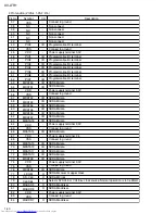
1-31
36
37~44
45
46
47
48
49
50
51
52
53~56
57
58
59
60
61~64
65
66
67
68
69
70
71
72
73
74
75
76
77
78
79
80
81
82
83
84
85
86
87
88
89
90
91
92
93
94
95
96
97
98
99
100
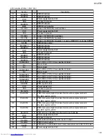
I
I/O
-
I
I
I
-
-
I
I
-
-
-
-
-
-
O
O
O
O
I
-
-
-
O
-
-
-
-
-
I
O
-
O
O
O
-
-
-
-
I
I
-
-
I
-
-
I
I
-
-
I
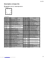
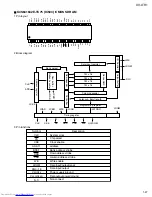
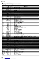
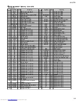
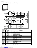
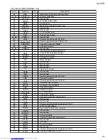
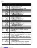
Pin No.
Symbol
NRD
CPUDT7~0
CLKOUT1
MMOD
NRST
MSTPOL
SCLOCK
SDATA
OFTR
BDO
PWM1~4
VDD3
DRAMVDD18
DRAMVSS
VSS
PWM5~8
TBAL
FBAL
TRSDRV
SPDRV
FG
TILTP
TILT
TILTN
TX
DTRD
IDGT
VDD18
VSS
VDD3
OSCI1
OSCO1
VSS
TSTSG
VFOSHORT
JLINE
AVSSD
ROUT
LOUT
AVDD
VCOF
TRCRS
CMPIN
LPFOUT
LPFIN
AVSS
HPFOUT
FPFIN
CSLFLT
RFDIF
AVDDC
PLFLT2
I/O
Description
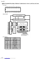
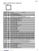
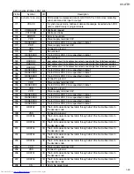
3.Pin function (MN103S28EGA : 2/4)
Read signal input from system controller
System control data
Non connect
Test mode switch signal
System reset
Master terminal polarity switch input
Non connect
Non connect
Off track signal input
Drop out signal input
Non connect
Power supply terminal for I/O (3.3V)
Power supply terminal for DRAM (1.8V)
Connect to ground for DRAM
Connect to ground
Non connect
Tracking balance adjustment output
Focus balance adjustment output
Traverse drive output
Spindle drive output
Motor FG input
Non connect
Non connect
Non connect
Digital output signal
Non connect
Non connect
Power supply terminal for I/O (1.8V)
Connect to ground
Power supply terminal for I/O (3.3V)
Oscillation input 16.9MHz
Oscillation output 16.9MHz
Connect to ground
Calibration signal
VFO short output
J-line setting output
Connect to ground for analog circuit
Non connect
Non connect
Power supply terminal for analog circuit (3.3V)
JFVCO control voltage
Input signal for track cross formation
Non connect
Non connect
Pull-up to VHALF
Connect to ground for analog circuit
Non connect
HPF input
Pull-up to VHALF
Non connect
Power supply terminal for analog circuit (3.3V)
Connect to capacitor 2 for PLL

