XV-C3SL
15
3.2.3
Removing the pickup
(See Fig.16 and 18)
(1) Remove the screw
I
attaching the
T
spring (S) and the
shaft holder. Remove also the plate.
ATTENTION:
When reattaching,make sure that the T spring (S)
presses the shaft.
(2) Pull out the part
l
of the shaft upward. Move the part
m
in
the direction of the arrow and detach from the spindle
base.
(3) Disengage the joint
n
of the pickup and the shaft in the di-
rection of the arrow.
(4) Pull out the shaft from the pickup.
(5) Remove the two screws
J
attaching the actuator.
(6) Disengage the joint of the actuator and the lead spring.
Pull out the lead spring.
Fig.15
The spring must be under the shaft when you
install pick-up.
Fig.16
Fig.17
3.2.4
Removing the shaft holder / shaft
(See Fig.18)
(1) Remove the screw
K
attaching the shaft holder.
(2) Remove the shaft.
Fig.18
Summary of Contents for XV-C3SL
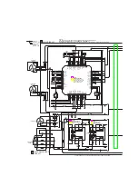
Page 23: ...XV C3SL 23 4 6 Troubleshooting 4 6 1 Servo volume Fig 14 ...
Page 30: ...XV C3SL 30 5 6 BA6664FM X IC251 3Phase Motor Driver Pin layout Block diagram ...
Page 43: ...XV C3SL 43 5 18 SI 3033LSA X IC952 DC Regulator Block diagram ...
Page 49: ...XV C3SL 49 ...
Page 72: ...XV C3SL 2 6 MEMO ...


