background image

3-79

3-80

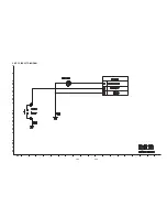
3. KEY P.C.BOARD

(TOP VIEW)

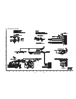
4. TIMER P.C.BOARD

(TOP VIEW)

(BOTTOM VIEW)

(BOTTOM VIEW)

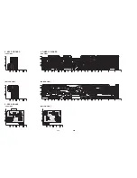
5. D5 P.C.BOARD

(TOP VIEW)

(BOTTOM VIEW)

Summary of Contents for XV-BP1A

Page 1: ...MODEL XV BP1UB XV BP1A SERVICE MANUAL P NO AFN73065097 JULY 2009 MODEL XV BP1UB XV BP1A BLU RAY DISC PLAYER ...

Page 2: ...1 1 CONTENTS SECTION 1 SUMMARY SECTION 2 CABINET MAIN CHASSIS SECTION 3 ELECTRICAL SECTION 4 HL 05P LOADER PART SECTION 5 REPLACEMENT PARTS LIST ...

Page 3: ...ODUCT SAFETY SERVICING GUIDELINES FOR BLU RAY DISC PLAYER PRODUCTS 1 3 SERVICING PRECAUTIONS 1 4 General Servicing Precautions Insulation Checking Prodedure Electrostatically Sensitive ES Devices SOFTWARE UPGRADE 1 5 SPECIFICATIONS 1 6 ...

Page 4: ...line plug has not been defeated 3 Soldering must be inspected to discover possible cold solder joints solder splashes or sharp solder points Be certain to remove all loose foreign par ticles 4 Check for physical evidence of damage or deterioration to parts and compo nents for frayed leads or damaged insulation including the AC cord and replace if necessary 5 No lead or component should touch a hig...

Page 5: ...onductive Parts include Metal panels Input terminals Earphone jacks etc Electrostatically Sensitive ES Devices Some semiconductor solid state devices can be damaged easily by static electricity Such components commonly are called Electrostatically Sensitive ES Devices Examples of typical ES devices are integrated circuits and some field effect transistors and semiconductor chip components The foll...

Page 6: ... JVC_BD_310M ROM Insert a upgrading disc or USB Show help message for disc upgrade as follows in the case of Back End program Front End program Press play key to upgrade and it will show progress information After completing upgrade then power is off SOFTWARE UPGRADE ...

Page 7: ... RCA jack x 1 Pb Pr 0 7V p p 75Ω RCA jack x 2 HDMI OUT video audio 19pin HDMI standard Type A ANALOG AUDIO OUT 2 0Vrms 1kHz 0dB 600Ω RCA jack L R x 1 DIGITAL OUT COAXIAL 0 5V p p 75Ω RCA jack x 1 DIGITAL OUT OPTICAL 3V p p Optical jack x 1 System Laser Semiconductor laser wavelength 405nm 650nm Signal system Standard NTSC Color TV system Frequency response 20Hz to 20kHz 48kHz 96kHz 192kHz sampling...

Page 8: ...2 1 SECTION 2 CABINET MAIN CHASSIS CONTENTS DISASSEMBLY INSTRUCTIONS 2 2 EXPLODED VIEWS 2 3 1 Cabinet and Main Frame Section 2 3 2 DEck MECHANISM SECTION HL 05P 2 4 3 Packing Accessory Section 2 5 ...

Page 9: ...nel to seperate the top cover 3 Push the top cover backward to seperate the top cover completely 4 Remove the nine front panel hooks four hooks on the top two hooks on the both side and three hooks on the bottom to seperate the front panel 5 It is the feature that the top and front panel are seperated ...

Page 10: ... location no a50 state in exploded views 462 250 468 B CABLE4 c 468 A47 SMPS BOARD MAIN BOARD a 468 A46 468 468 468 A44 465 320 465 260 261 261 261 470 KEY BOARD a TIMER BOARD 283 284 287 275 275 452 452 452 452 CABLE2 PN401 A50 A43 A43A EXPLODED VIEWS 1 Cabinet and Main Frame Section MaIn bOarD D5 bOarD CabLE6 a51 JaPanESE MODEL OnLY 300 CABLE3 ...

Page 11: ...30 A002 1431 1002 A001 1001 1003 1026 1013 1017 1433 1016 1015 1012 1020 1020 1046 CABLE3 A52 LOADER BOARD CABLE4 1049 A60 OPTIONAL PART Refer to HOW TO USE THE BAR CODE SCAN TOOL Page4 11 4 13 after replacing A002 A52 and 1049 Service Notice 1019 1018 1043 1045 A005 2 4 ...

Page 12: ...2 5 3 Packing Accessory Section 808 Battery 812 Plug Ass y 2way 811 Plug Ass y 1way 804 Bag 803 Packing 900 Remote Control 801 Instruction Ass y 803 Packing 802 Box ...

Page 13: ...2 6 MEMO ...

Page 14: ...AMS 3 46 1 OVERALL BLOCK DIAGRAM 3 46 2 SMPS BLOCK DIAGRAM 3 47 3 SYSTEM BLOCK DIAGRAM 3 48 4 MT8520 DDR2 SDRAM NAND FLASH EEPROM BLOCK DIAGRAM 3 49 5 MT8520 HDMI ETHERNET USB AV BLOCK DIAGRAM 3 50 6 MICOM AND TIMER BLOCK DIAGRAM 3 51 7 SMPS POWER SIGNAL BLOCK DIAGRAM 3 52 8 MAIN BOARD POWER SIGNAL BLOCK DIAGRAM 3 53 9 TIMER MICOM POWER SIGNAL BLOCK DIAGRAM 3 54 10 LEVEL SHIFTER CEC EFUSE BLOCK DI...

Page 15: ...sue is a problem with the disc Multiple discs displaying the problem could indicate the BD lens needs to be cleaned Recommend the customer use a lens cleaner on the BD A lens cleaner is available at any local electronics retailer Do lines appear when watching a TV program NO YES Lines appearing when watching a TV program indicates an issue with the display If the TV program is fine then connect th...

Page 16: ...is available at any local electronics retailer Do lines appear when watching a TV program NO YES Ghosting appearing when watching a TV program indicates an issue with the display If the TV program is fine then connect the BD to another input on the display to determine if the problem is following the BD Does ghosting appear when the BD is connected to another TV NO YES Connect the BD to another TV...

Page 17: ...is available at any local electronics retailer Does rolling appear when watching a TV program NO YES Rolling appearing when watching a TV program indicates an issue with the display If the TV program is fine then connect the BD to another input on the display to determine if the problem is following the BD Does rolling appear when the BD is connected to another TV NO YES Connect the BD to another ...

Page 18: ... is available at any local electronics retailer Does shaking appear when watching a TV program NO YES Shaking appearing when watching a TV program indicates n issue with the display If the TV program is fine then connect the BD to another input on the display to determine if the problem is following the BD Does shaking appear when the BD is connected to another TV NO YES Connect the BD to another ...

Page 19: ...ailable at any local electronics retailer Does blurriness appear when watching a TV program NO YES Blurriness appearing when watching a TV program indicates an issue with the display If the TV program is fine then connect the BD to another input on the display to determine if the problem is following the BD Does blurriness appear when the BD is connected to another TV NO YES Connect the BD to anot...

Page 20: ...ble to watch TV programming NO YES If the customer is not able to watch television then he may have a problem with his television especially if the cable signal comes through on a different input If the customer can not get a TV program then he still may have a problem with the particular input on his TV Can the customer connect the BD to another TV NO YES Have the customer connect the BD to anoth...

Page 21: ... able to watch television then he may have a problem with his television especially if the cable signal comes through on a different input If the customer can not get a TV program then he still may have a problem with the particular input on his TV Can the customer connect the BD to another TV NO YES Have the customer connect the BD to another TV in order to determine if the problem is the BD or t...

Page 22: ...television then he may have a problem with his television especially if the cable signal comes through on a different input If the customer can not get a TV program then he still may have a problem with the particular input on his TV Can the customer connect the BD to another TV NO YES Have the customer connect the BD to another TV in order to determine if the problem is the BD or the TV Refer to ...

Page 23: ...o watch television then he may have a problem with his television especially if the cable signal comes through on a different input If the customer can not get a TV program then he still may have a problem with the particular input on his TV Can the customer connect the BD to another TV NO YES Have the customer connect the BD to another TV in order to determine if the problem is the BD or the TV R...

Page 24: ...iant NO YES Make sure the display is HDCP compliant when using a DVI or HDMI connection A lack of HDCP compliancy on the display may cause an invalid format or format not supported message to appear It can also cause a copy protection OSD to appear Has the customer tried the device on another display NO YES Ask the customer to connect the device to another display If the device starts working then...

Page 25: ...scs in the owners manual Multiple discs displaying the problem indicates a problem with the BD player Does color appear when watching a TV program NO YES If the cable or satellite programming is connected through another input and the customer does not get color the customer has a problem with his television If a TV program does have the color the problem may be the BD player the cables being used...

Page 26: ...or fine when watching a TV program NO YES If the cable or satellite programming is connected through another input and the customer does not get color the customer has a problem with his television If a TV program does have the color the problem may be the BD player the cables being used or the TV itself Is color fine when the BD is connected to another TV NO YES Connect the BD to another TV and p...

Page 27: ...le discs could indicate a lens cleaner is needed The customer can purchase a lens cleaner at any electronics retailer Problem occur when watching TV program NO YES No audio from a TV program on a different channel or input means there is a problem with the television If a TV program does have the audio the problem may be the BD player the cables being used or the TV itself Does the problem occur w...

Page 28: ...lens cleaner at any electronics retailer Problem occur when watching TV program NO YES Distorted audio from a TV program on a different channel or input means there is a problem with the television If a TV program does have the audio the problem may be the BD player the cables being used or the TV itself Does the problem occur when DVD is connected to another TV NO YES Audio is fine when the BD is...

Page 29: ...multiple tapes and discs NO YES YES If the issue only shows up on one disc then the problem is with that disc Have the customer try multiple tapes or discs If the issue happens on multiple discs and tapes then ask the customer to try a lens or a head cleaner Has the customer connected to another TV NO Ask the customer to connect the product to another TV If the issue persists try another set of ca...

Page 30: ...it plugged into a surge protector NO YES Make sure the surge protector is plugged into a wall outlet Also make sure the surge protector is turned on or does not need to be reset due to a recent surge Does the unit work when plugged into another outlet NO YES Test the unit in another outlet If the unit works then the problem is the outlet where the unit was connected If the issue is the BD then set...

Page 31: ...customer initialized a DVD RW in VR mode make sure the owners manual has the RW logo to show compatibility for the VR format Did the customer burn the disc in a computer NO YES Make sure the customer burned a compatible format such as VCD SVCD or DivX Make sure the file meets the specifications required for the player to play the disc Check the owners manual for specifications Disc may still not b...

Page 32: ... the unit does not respond after the reset arrange for service on the BD 5 3 Unit Locks Up Unit does not respond to any commands Does the open close button on the unit work NO YES Press the open close button on the unit If the disc ejects troubleshoot the remote using the Remote Control not working call flow Has the customer reset the unit NO Ask the customer to reset the unit by unplugging the un...

Page 33: ...ies are new and fresh The batteries do not need to come from a spare battery drawer Do not mix used and new batteries Is the remote working at all NO YES YES If the remote does not work anything then walk the customer through a remote drain Remove the batteries from the remote control Then press and hold any button down for a minute This will drain the power out of the remote and reset it Universa...

Page 34: ...er initialized a DVD RW in VR mode make sure the owners manual has the RW logo to show compatibility for the VR format Did the customer burn the disc in a computer NO YES Make sure the customer burned a compatible format such as VCD SVCD or DivX Make sure the file meets the specifications required for the player to play the disc Check the owners manual for specifications Disc may still not be comp...

Page 35: ...initialized a DVD RW in VR mode make sure the owners manual has the RW logo to show compatibility for the VR format Did the customer burn the disc in a computer NO YES Make sure the customer burned a compatible format such as VCD SVCD or DivX Make sure the file meets the specifications required for the player to play the disc Check the owners manual for specifications Disc may still not be compati...

Page 36: ...th America The player can play only DVD discs labeled same as the rear of the unit Is the disc locking up on a disclaimer screen when the customer presses play NO The disc locking up on a feature needs to be reported to Q E See instructions on reporting problems to Q E For a work around the problem advise the customer to access the chapter list Start play back from chapter 1 to start the movie and...

Page 37: ... the BD player aspect ratio is set to the appropriate setting depending on the aspect ratio of the TV If the customer chose 4 3 Letterbox then bars will appear on the top and bottom The customer can choose the panscan setting to get rid of the bars What is the resolution of the BD player set at NO YES Try changing the resolution to 576p 720p 1080i and 1080p resolution require a widescreen aspect r...

Page 38: ...opy protected discs will not upconvert when HDCP is not found on the input or output Is the customer using an HDMI or DVI cable NO YES Regular discs can convert to 1080p over the HDMI output and only the HDMI output The TV has to have HDCP compliancy on the HDMI input The display has to accept the resolution 480p 720p 1080i or 1080p Is the customer using an HDMI to DVI cable NO YES Some movie comp...

Page 39: ... from one disc to another the lens will change which is what causes the delay Blu Ray require different lasers to read the discs 6 Blu RAY Player 6 1 Slow Loading Times for BDs Why does it take so long to boot my BD NO The booting times for the BD is 20 seconds When the set is booted it takes a little long time to loading the OS program 6 2 Booting Times ...

Page 40: ... Unit can support BD2 0 so that network function is active in the BD disc Why is not the item downloaded through the network NO Make sure the customer insert the LAN cable into the Ethernet jack Make sure the network is active If it is active the disc may have a problem If not active see the network section of OM 6 3 Ethernet Port The purpose of the ethernet port on the unit ...

Page 41: ...ration Network Settings NO YES If there is a DHCP Dynamic Host Configuration Protocol server on the local area network LAN this player will automatically be allocated an IP address If there is no DHCP server on the network and you want to set the IP address manually select Static IP then set the IP Address Subnet Mask Gateway and DNS Server using IP Setting option Checking Network Configuration NO...

Page 42: ...speed of 1 5Mbps For the best quality picture a connection speed of 4 0Mbps is required Do not have any other online activity on your network NO YES Your connection may be affected by other activity on your network such as online gaming file sharing or other video streaming Test your bandwidth NO You can test your bandwidth at one of these sites http www speakeasy net speedtest http www speedtest ...

Page 43: ...lace F101 same fuse NO Is the F101 normal Replace BD101 NO Is BD101 normal YES Replace R101 NO Is the R101 normal YES YES Is D102 normal Check or replace the D102 NO Is VCC 13V 27V supplied to IC101 Pin4 YES Replace IC103 NO Is there about 2 5V at the IC103 Pin1 YES YES Replace IC102 NO Is the IC102 normal ...

Page 44: ...D132 Is the Vcc 5 5V supplied to D132 anode NO Check the DVD CTL H signal from µ com Is the IC152 Pin4 H YES YES YES NO No 12V_A Check or Replace the IC151 Check or Replace the D121 Is the Vcc 13 5V supplied to IC151 Pin1 NO Check the DVD CTL H signal from µ com Is the IC151 Pin4 H YES YES YES NO No 12V_L Check or Replace the IC154 Check or Replace the D121 Is the Vcc 13 5V supplied to IC154 Pin1 ...

Page 45: ... WAIT Display on VFD OK Front I F cable connection OK NO NO YES VFD power cable connect VFD power cable connection OK NO YES YES YES Proper display cable connect LG LOGO display on monitor OK Display cable connection OK NO NO YES 2 POWER ON ELECTRICAL TROUBLESHOOTING GUIDE ...

Page 46: ...ange R516 About 625kHz Serial Clock OK NO YES IC502 Change R523 about 500kHz OK NO YES DIG501 Change Check SMPS READING Display on VFD OK CN701 Pin5 12V Pin7 5V Pin2 2 2V Pin11 5 3VA YES IC202 IC203 IC204 Change CA207 5 3VA CA210 1 2V CA211 5V NO NO YES X301 Change X301 27MHz OK NO X102 Change X302 25MHz OK NO YES YES Check IC301 System part OK 3 System Part ELECTRICAL TROUBLESHOOTING GUIDE ...

Page 47: ...mponent YPbPr Video Out Re soldering YES NO L906 3 3V OK Re soldering YES NO C913 C914 C915 Signal OK Re soldering YES NO R923 R924 R925 Signal OK Re soldering YES NO JK904 Soldering OK Component Video OK ELECTRICAL TROUBLESHOOTING GUIDE ...

Page 48: ...video no display IC301 Check YES NO 5 CVBS Video Out C910 Video signal input OK IC901 Check YES NO R913 Video signal output OK Re soldering YES NO JK904 Soldering OK CVBS Video OK ELECTRICAL TROUBLESHOOTING GUIDE ...

Page 49: ...PDIF OPTICAL ELECTRICAL TROUBLESHOOTING GUIDE No Audio S PDIF OPTICAL audio out OK IC204 Check JK903 Red Lighting OK C917 Digital Audio output OK JK903 Pin2 5 0V OK NO NO NO YES JK903 Re soldering IC301 Check YES YES ...

Page 50: ...V_AUDIO OK Q905 Pin2 LOW NO Q902 Re soldering YES IC903 Pin 6 7 8 I2S Output OK NO IC301 Check YES IC903 Pin 14 15 audio output before Amp OK NO IC903 Check YES R949 R950 JK904 Pin2 5 soldering OK NO Re soldering YES CA907 CA908 audio output OK NO IC904 Check YES 7 Audio ANALOG ELECTRICAL TROUBLESHOOTING GUIDE ...

Page 51: ...soldering JK902 Soldering OK NO JK902 Pin18 VCC 5V OK L902 soldering OK NO NO Re soldering YES YES IC204 Pin 4 Check YES JK902 Pin15 16 SCL SDA OK NO Check HDMI Voltage Level Shifter YES JK902 Pin19 2 0V Voltage 5 3V OK NO TV hot plug detect signal check from IC301 YES ...

Page 52: ...3 39 1 2 5 4 3 6 7 WAVEFORMS 1 System Part 1 MT8520 XTAL 27MHz 1 2 5 4 3 6 1 MT8520 XTAL 25MHz for SATA Loader 2 IC301 MT8520 IC301 MT8520 ...

Page 53: ...3 40 2 System Part 2 SYSTEM MEMORY MT8520 DDR2_A_BA 0 3 MT8520 DDR2_A_WE 2 5 4 3 6 4 MT8520 DDR2_A_CAS 5 MT8520 DDR2_A_CLK0 6 ...

Page 54: ...3 41 3 Video Part 1 100 Full Color bar 7 9 10 8 11 14 CVBS_I 7 Y 8 Pb 9 Pr 10 ...

Page 55: ...3 42 4 Video Part 2 100 Full Color bar 9 8 11 14 13 12 CVBS 11 COMP_Y 12 COMP_Pb 13 COMP_Pr 14 ...

Page 56: ...3 43 5 AUDIO PART S PDIF 15 17 16 18 19 21 ASPDIF 15 ...

Page 57: ...3 44 6 HDMI PART 17 16 18 19 21 20 HDMI_SDA 16 HDMI_SCL 17 HDMI_CLK 18 HDMI_DATA 19 ...

Page 58: ...3 45 7 FRONT I F PART 21 20 T_TX 20 R_RX 21 ...

Page 59: ...3 46 BLOCK DIAGRAMS 1 OVERALL BLOCK DIAGRAM ...

Page 60: ...3 47 2 SMPS BLOCK DIAGRAM ...

Page 61: ...3 48 3 SYSTEM BLOCK DIAGRAM ...

Page 62: ...3 49 4 MT8520 DDR2 SDRAM NAND FLASH EEPROM BLOCK DIAGRAM ...

Page 63: ...3 50 5 MT8520 HDMI ETHERNET USB AV BLOCK DIAGRAM ...

Page 64: ...t MAC 3 3VA IC501 uPD7BF0535GK Micom 5 3VA PVX01 Flash Micom D L TXD RXD TIMER_TX TIMER_RX 3 3VA 5 3VA CEC_RX CEC_TX IC505 CEC RC501 RCU Receiver REMOCON_IN KEY SUB KEY KEY_RTN0 BD_LED_CTRL LED502 507 IC502 PT6315 VFD Driver IC FLD_CLK FLD_DATA_OUT FLD_ENA_L P 01 15 G 01 06 DIG501 HNS 06SC41 LED501 LED401 STBY_LED Q203 ...

Page 65: ...3 52 7 SMPS POWER SIGNAL BLOCK DIAGRAM ...

Page 66: ...3 53 8 MAIN BOARD POWER SIGNAL BLOCK DIAGRAM ...

Page 67: ... 29VA PWR_CTRL_5 3VA 5 3VA 5 3VA IC501 uPD7BF0535GK Micom IC505 2SK3018 T106 2 5V Drive Nch MOS FET IC506 uPA672T MOS Field Effect TR PVX01 Flash Micom D L CN503 IC502 PT6315 VFD Driver IC 29VA PWR_CTRL_5 3VA 5V FD FD 29VA PWR_CTRL_5 3VA 5 3VA RC501 RCU Receiver HB1M2012_102JT HB1M2012_102JT 3 3VA 3 3VA ZD503 ...

Page 68: ...3 55 10 LEVEL SHIFTER CEC EFUSE BLOCK DIAGRAM ...

Page 69: ...3 56 MEMO ...

Page 70: ...Power IC154 are Defective WHEN SERVICING THIS CHASSIS UNDER NO CIRCUMSTANCES SHOULD THE ORIGINAL DESIGN BE MODIFIED OR ALTERED WITHOUT PERMISSION FROM THE JVC ALL COMPONENTS SHOULD BE REPLACED ONLY WITH TYPES IDENTICAL TO THOSE IN THE ORIGINAL CIRCUIT SPECIAL COMPONENTS ARE SHADED ON THE SCHEMATIC FOR EASY IDENTIFICATION THIS CIRCUIT DIAGRAM MAY OCCASIONALLY DIFFER FROM THE ACTUAL CIRCUIT USED THI...

Page 71: ...3 60 3 59 2 POWER TIMER USB CIRCUIT DIAGRAM ...

Page 72: ...3 61 3 62 3 MT8520 1 CIRCUIT DIAGRAM ...

Page 73: ...3 63 3 64 4 MT8520 2 CIRCUIT DIAGRAM ...

Page 74: ...3 65 3 66 5 KEY CIRCUIT DIAGRAM ...

Page 75: ...3 67 3 68 6 TIMER CIRCUIT DIAGRAM ...

Page 76: ...3 69 3 70 7 DDR2 SDRAM CIRCUIT DIAGRAM ...

Page 77: ...3 71 3 72 8 NAND FLASH ETHERNET CIRCUIT DIAGRAM ...

Page 78: ...3 73 3 74 9 AV HDMI CIRCUIT DIAGRAM ...

Page 79: ...3 75 3 76 PRINTED CIRCUIT BOARD DIAGRAMS 1 MAIN P C BOARD TOP VIEW BOTTOM VIEW ...

Page 80: ...3 77 3 78 2 SMPS P C BOARD TOP VIEW BOTTOM VIEW ...

Page 81: ...3 79 3 80 3 KEY P C BOARD TOP VIEW 4 TIMER P C BOARD TOP VIEW BOTTOM VIEW BOTTOM VIEW 5 D5 P C BOARD TOP VIEW BOTTOM VIEW ...

Page 82: ...DE SCAN SYSTEM CONFIGURATION 4 11 2 PICK UP BAR CODE SCAN TOOL CONFIGURATION 4 11 3 RUNNING BAR CODE SCAN TOOL 4 12 4 BAR CODE SCAN PROCEDURE 4 13 INTERNAL STRUCTURE OF THE PICK UP 4 14 1 OPTICAL LAYOUT 4 14 2 SF BD412 PDIC COMPOSITION 4 15 3 PICK UP CONNECTOR TERMINAL PIN ASSIGNMENTS 4 16 MAJOR IC INTERNAL BLOCK DIAGRAM AND PIN DESCRIPTION 4 17 1 LIC501 MT8575 BLU RAY SIGNAL PROCESSOR SINGLE CHIP...

Page 83: ... cable only on interface cable for NO Reset or Power ON YES YES YES Check the LIC902 and LIC902 input voltage 3 3V Pin 3 NO Power Is the pin2 of LIC903 1 2V YES YES Check the LX501 25MHz Check the LIC501 NO Are the LX501 oscillating YES YES Check the AVCC 5volt and Reset Circuit LR610 LR855 LC5B0 NO Does the Pin120 Reset in of LIC501 change 0V to 1 63V at the power supply initial input mode Check ...

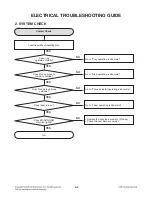
Page 84: ...ES Go to Sled operating is abnormal NO Does Pick up move to Inside or outside YES Go to Focus actuator operating is abnormal NO Does Pick up lens move up down YES Go to Laser operating is abnormal NO Does laser turn on YES Replace the traverse assembly Pick up Check the new firmware version NO Does BD DVD ROM disc play rightly YES YES 2 SYSTEM CHECK ...

Page 85: ... Is there Tray control signal output LIC501 Pin55 YES YES Is there tray drive voltage output LIC201 Pin27 28 NO NO NO Check the serial flash operation Check the SATA communication between B end MPEG Chip Go to reset or power check Check the connection from LIC501 Pin55 to LIC201 Pin4 Check the LIC201 YES Is there tray drive voltage output Loading Motor NO Check the connector LPF301 and FFC cable c...

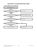
Page 86: ...utput LIC501 Pin56 57 Check the PCB pattern and components between LIC501 and LIC201 sled signals NO Is there sled drive voltage input LIC201 Pin2 3 YES Check the LIC201 NO Is there sled drive voltage output LIC201 Pin6 8 9 10 YES NO Is there sled drive voltage output LPM302 Pin1 2 3 4 YES Replace the sled motor YES 4 SLED OPERATING IS ABNORMAL ...

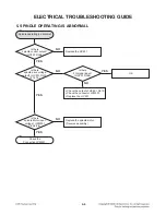
Page 87: ...e voltage output LIC201 Pin12 13 14 16 Is there FG signal input LIC501 Pin96 YES NO Is there spindle control output LIC501 Pin58 NO NO Check the output of LIC201 Pin19 Check the connector LPM301 Replace the LIC201 Replace the LIC501 OK YES Is there spindle Motor input voltage LPM301 Pin3 4 5 6 NO Replace the spindle motor Traverse assembly YES YES ...

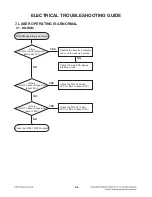
Page 88: ...connection of LIC501 Pin54 Replace the LIC501 NO Is there focus search control signal input LIC201 Pin40 Check the LIC201 NO Is there focus search drive voltage output LIC201 Pin34 35 YES Check the signal pattern and application components NG Check the connection LCN700 Pin1 2 YES OK 6 FOCUS ACTUATOR OPERATING IS ABNORMAL ...

Page 89: ... YES Replace the traverse assembly and scan the pick up barcode Is there TR LQ122 base voltage input about 8 0V YES Check the TR LQ122 and VCC for BD LD about 9 2V Check the main PCB pick up interface circuit NO NO 7 LASER OPERATING IS ABNORMAL 7 1 BD ROM Is there TR LQ112 base voltage input about 1 33V YES Check the TR LQ112 and VCC for BD LD about 9 2V NO ...

Page 90: ... 2 27V 25 C YES Replace the traverse assembly and scan the pick up barcode Is there TR LQ121 base voltage input about 3 5V YES Check the TR LQ121 Check the main PCB pick up interface circuit NO NO 7 2 DVD ROM Is there TR LQ111 base voltage input about 1 42V YES Check the TR LQ111 NO ELECTRICAL TROUBLESHOOTING GUIDE ...

Page 91: ... input about 1 79V 25 C YES Replace the traverse assembly and scan the pick up barcode Is there TR LQ120 base voltage input about 3 6V YES Check the TR LQ120 Check the main PCB pick up interface circuit NO NO Is there TR LQ110 base voltage input about 1 37V YES Check the TR LQ110 NO ELECTRICAL TROUBLESHOOTING GUIDE ...

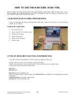
Page 92: ...r Code Scan Tool Loader Tester 3 2D Bar Code Scanner 4 Target Loader Ass y 5 USB to SATA Connector 6 Power Supply 2 PICK UP BAR CODE SCAN TOOL CONFIGURATION The Loader Tester is the Application Tool for FA Test and also Bar Code Scan The Bar Code Scan is the one of functions in the Loader Tester Therefore the Bar Code scan Users should check only Bar Code up in the Loader Tester Loader Tester Prog...

Page 93: ...wing screen appears Before you start to click Start button remind these 1 Test Mode Start should be selected 2 Check only Bar Code 3 Click START Select Test Mode Start Status and Result Click START in order to insert Bar Code Values Check only Bar Code Bar Code Values Display Result Output Window ATAPI Command Display ...

Page 94: ...not be detected please plug off and on again the USB to SATA connector to the PC and wait for 15 seconds 7 Sled will move the innermost 8 Focus on the target of Bar Code and Pull the trigger of Bar Code scanner until Bar Code can be scanned to the Bar Code scan Tool Loader Tester 9 If Bar Code scan succeeds OK will display in the result windows However Bar Code scan fails NG will display in the re...

Page 95: ...4 14 INTERNAL STRUCTURE OF THE PICK UP 1 OPTICAL LAYOUT 405nm LD PD PD 650 780nm LD DVD CD Layout Blu ray Layout 2 OBL type DVD CD BD ...

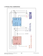
Page 96: ...A D SA SD SW SW2 SW1 SW3 RF RF RF RF Vcc Vref GND GND Vref Vcc For DVD CD For Blue RF RF SA SD A D SW3 SW SW2 SW1 GND Vref Vcc Two pins for gain changeover of BD Output signals share the pin in every mode SW SW1 SW2 SW3 are controlled by DSP IC ...

Page 97: ...DVD CD 24 RF RF output for BD DVD CD 25 SWB2 SW for PDIC BD Gain and sleep 26 SWB1 SW for PDIC BD Gain and sleep 27 VREF_PD PDIC Reference Supply Terminal 2 1V 28 VCC_ 5PD PDIC Power Terminal 5V 29 GND_PD GND for PDIC 30 SW 2 Wavelength PDIC DVD CD Sleep Changeover SW 31 GND1 LDD HFM IC Monitor GND for LD HFM IC 32 LDI_BD LD control for BD_LD 33 LDI_CD LD control for CD_LD 34 LDI_DVD LD control fo...

Page 98: ... AVDD33_2 14 INE 15 INF 16 ING 17 INH 18 AGND_2 19 FOIP 20 FOIN 21 VDD12_2 22 FPDODVD 23 FPDOCD 24 RFIN 25 RFIP 26 RFIP2 27 RFIN2 28 REG_CAP 29 AGND_3 30 AVDD33_3 31 AVDD12_3 32 AVDD12_4 33 LGO1P 34 LGO1N 35 LGO2P 36 LGO2N 37 LGO3P 38 LGO3N 39 LGO4P 40 LGO4N 41 LGO5P 42 LGO5N 43 AVDD33_4 44 LDD_SDIO 45 LDD_CLK 46 LDD_SEN 47 GAINSW 48 GAINSW2 49 GAINSW3 50 FMO3 51 FMO4 52 TLO 53 TRO 54 FOO 55 TRAYP...

Page 99: ...it Laser Power Control Logic Tray Actuator Control Unit Servo Control Unit Spindle Control System Control Unit SATA Interface Unit 1M word SDRAM Buffer Memory Controller Unit BD DVD CD Decode Engine ATIP ADIP Pre_pit Sync Protection ECC check Target Search SATA Transmit Receive PUH signal PUH signal Panel Control Laser Control Tray Actuator Control ...

Page 100: ...to Power Control for Laser 6 22 FPDODVD Analog Input Laser Power Monitor Input for DVD APC Differential positive input 23 FPDOCD Analog Input Laser Power Monitor Input for CD APC Differential negative input 121 VRDCO Analog Output Output Voltage of Laser Diode Control in Read APC 122 VRDC1O Analog Output Output Voltage 1 of Laser Diode Control in Read APC 123 VRDC2O Analog Output Output Voltage 2 ...

Page 101: ...μ P 56 FMO Analog Output Feed motor control PWM output 57 FMO2 Analog Output Feed motor 2 control PWM output 58 DMO Analog Output Disk motor control output PWM output 3 3V LVTTL I O 96 FG 5V tolerance 1 Motor Hall sensor input The pin is spike free at power on stage 2mA PDR 75K pull up SATA Interface 10 77 SVDD33 Analog Power 3 3V Power supply for SATA 3 3V circuitry 78 SPLLVDD12 Analog Power 1 2V...

Page 102: ... on stage Alternate function General I O 87 GIO4 3 3V LVTTL I O General IO 88 GIO5 3 3V LVTTL I O General IO 89 GIO6 3 3V LVTTL I O General IO 90 GIO7 MUTE3 General IO The pin is spike free at power on stage 91 GIO8 General IO General IO The pin is spike free at power on stage 92 GIO9 SPOKE The pin is not allowed to pull up in circuit layout Alternate function Spoke input PC RS232 serial receive d...

Page 103: ...EMF EDTECTER SWICHING Commutation STARTER PWM CIRCUIT 6 4MHz STTH For SLIDE 7 13 2V FG x3 Reverse datact CTL TEST mode Gain Select SPM Current gain 0 88A V Current gain 3A V 0 6A V Frequency 75kHz Current gain 0 88A V PWM CIRCUIT PWM CIRCUIT Cuurrent sense Cuurrent sense Cuurrent sense Frequency 75kHz Frequency 150kHz TEST SPGS EN 1 EN 2 ENABLE DSP DSP DSP ACTFLG ACTRST SLLIM SL1 SL1 GND SL1IN SL2...

Page 104: ...Frequency generator output 20 EN1 Input terminal for enable 1 21 EN2 Input terminal for enable 2 22 VM1 Motor Power Supply 1 for Spindle 23 SPGS Input terminal for gain select SPM 24 STTH Reference voltage for spindle start up 25 ACTRST Pickup protect Reset 26 VM3 Power Supply3 for Loading 27 LO Loading non inverted output 28 LO Loading inverted output 29 GND GND 30 TO Tracking inverted output 31 ...

Page 105: ...4 24 MEMO ...

Page 106: ...4 26 4 25 CIRCUIT DIAGRAM ...

Page 107: ...0 63 0 00 64 0 00 65 3 30 66 3 30 67 0 00 68 0 00 69 3 30 70 0 00 71 1 19 72 3 27 73 3 27 74 OSC 75 OSC 76 3 24 77 3 24 78 1 16 79 0 00 80 1 19 81 1 19 82 1 19 83 0 00 84 1 19 85 1 19 86 1 19 87 PULSE 88 0 00 89 0 00 90 2 87 91 0 00 92 0 00 93 PULSE 94 PULSE 95 0 00 96 PULSE 97 3 30 98 0 00 99 0 00 100 0 00 101 PULSE 102 3 30 103 3 30 104 3 30 105 3 30 106 3 30 107 3 30 108 3 30 109 3 30 110 1 19 ...

Page 108: ...4 29 4 30 PRINTED CIRCUIT BOARD DIAGRAMS TOP VIEW ...

Page 109: ...4 31 4 32 BOTTOM VIEW ...

Reviews: