3-28
TRAINING MASTER FOR BLU-RAY (BD)
7. NETWORK
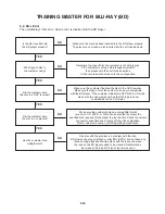
7-1. Network Setup
By connecting the unit to broadband internet, you can use Bd live feature
check the network
connection
NO
YES
connect the player’s lan port to the corresponding port
on your Modem router using a lan cable.
use a commercially available straight lan cable
(category 5/cat5 or better with rJ45 connector)
configuration network
Settings
NO
YES
if there is a dhcP (dynamic host configuration Protocol)
server on the local area network (lan), this player will automatically
be allocated an iP address. if there is no dhcP server on the network
and you want to set the iP address manually, select [Static iP]
then set the [iP address], [Subnet Mask], [Gateway]
and [dnS Server] using [iP Setting] option
checking network
configuration
NO
Select [netWork] on the [Setup] menu. and then Select [iP Mode]
option on the [netWork] menu. and then check the network status
indicator changes according to network configuration.
Summary of Contents for XV-BP1A
Page 13: ...2 6 MEMO ...
Page 54: ...3 41 3 Video Part 1 100 Full Color bar 7 9 10 8 11 14 CVBS_I 7 Y 8 Pb 9 Pr 10 ...
Page 56: ...3 43 5 AUDIO PART S PDIF 15 17 16 18 19 21 ASPDIF 15 ...
Page 57: ...3 44 6 HDMI PART 17 16 18 19 21 20 HDMI_SDA 16 HDMI_SCL 17 HDMI_CLK 18 HDMI_DATA 19 ...
Page 58: ...3 45 7 FRONT I F PART 21 20 T_TX 20 R_RX 21 ...
Page 59: ...3 46 BLOCK DIAGRAMS 1 OVERALL BLOCK DIAGRAM ...
Page 60: ...3 47 2 SMPS BLOCK DIAGRAM ...
Page 61: ...3 48 3 SYSTEM BLOCK DIAGRAM ...
Page 62: ...3 49 4 MT8520 DDR2 SDRAM NAND FLASH EEPROM BLOCK DIAGRAM ...
Page 63: ...3 50 5 MT8520 HDMI ETHERNET USB AV BLOCK DIAGRAM ...
Page 65: ...3 52 7 SMPS POWER SIGNAL BLOCK DIAGRAM ...
Page 66: ...3 53 8 MAIN BOARD POWER SIGNAL BLOCK DIAGRAM ...
Page 68: ...3 55 10 LEVEL SHIFTER CEC EFUSE BLOCK DIAGRAM ...
Page 69: ...3 56 MEMO ...
Page 71: ...3 60 3 59 2 POWER TIMER USB CIRCUIT DIAGRAM ...
Page 72: ...3 61 3 62 3 MT8520 1 CIRCUIT DIAGRAM ...
Page 73: ...3 63 3 64 4 MT8520 2 CIRCUIT DIAGRAM ...
Page 74: ...3 65 3 66 5 KEY CIRCUIT DIAGRAM ...
Page 75: ...3 67 3 68 6 TIMER CIRCUIT DIAGRAM ...
Page 76: ...3 69 3 70 7 DDR2 SDRAM CIRCUIT DIAGRAM ...
Page 77: ...3 71 3 72 8 NAND FLASH ETHERNET CIRCUIT DIAGRAM ...
Page 78: ...3 73 3 74 9 AV HDMI CIRCUIT DIAGRAM ...
Page 79: ...3 75 3 76 PRINTED CIRCUIT BOARD DIAGRAMS 1 MAIN P C BOARD TOP VIEW BOTTOM VIEW ...
Page 80: ...3 77 3 78 2 SMPS P C BOARD TOP VIEW BOTTOM VIEW ...
Page 105: ...4 24 MEMO ...
Page 106: ...4 26 4 25 CIRCUIT DIAGRAM ...
Page 108: ...4 29 4 30 PRINTED CIRCUIT BOARD DIAGRAMS TOP VIEW ...
Page 109: ...4 31 4 32 BOTTOM VIEW ...


