background image

31

English

TEXT COMPU LINK

1 (MASTER UNIT)

2 (SLAVE UNIT)

COMPU LINK- 3

(SYNCHRO)

TEXT COMPU LINK

JVC’s TEXT COMPU LINK remote control system allows you to transfer text information
recorded on the CD Text or MD among JVC audio components.
• Each component must have the same remote control system.

Connection with receiver (or amplifier)

This system enables text information on the MD to be displayed on the receiver (or
amplifier).
• If the receiver (or amplifier) has the on-screen function, you can display the text

information on any TV screen, and can do the following, using the on-screen function
while watching the TV screen:
– Operate this MD recorder.
– Assign titles to the MD and its tracks.

• If the CD player equipped with the TEXT COMPU LINK remote control system is also

connected to the receiver (or amplifier), you can record the track title information of the
CD Text onto an MD in its original form, when recording from the CD player.

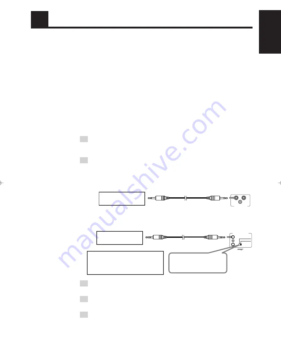
To use this control system, connect the receiver and this MD recorder as follows:

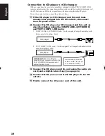
1 If the receiver (or amplifier) and this unit have already

been plugged into the AC outlets, disconnect their AC
power cords.

2 Connect the receiver and this unit as described below

using the COMPU LINK-3 (SYNCHRO) and TEXT COMPU
LINK jacks.

1

COMPU LINK-3 (SYNCHRO) jacks:  Use the supplied Compu Link cable (with
the monaural mini-plugs: black).

2

TEXT COMPU LINK jacks:  Use the supplied Text Compu Link cable (with the
stereo mini-plugs: green).

3 Connect the receiver and this unit using the audio pin

cord (and a digital cable if any) (see page 6).

4 Connect the AC power cords of this unit to the AC

outlets.

5 Finally connect the AC power cord of the receiver.

For further details on how to use the TEXT COMPU LINK remote control system, refer to
the manual supplied with your receiver (or amplifier).

Receiver

Receiver

Set the MASTER/SLAVE
selector on the rear panel
to “2 (SLAVE UNIT).”

IMPORTANT: Without setting the
MASTER/SLAVE selector correctly, the
TEXT COMPU LINK remote control
system does not work.

 EN30-40.XM-448BK[E]/f

99.3.4, 9:52 AM

31

Summary of Contents for XM-448BK

Page 1: ...al No LVT0222 003A E INSTRUCTIONS BEDIENUNGSANLEITUNG MANUEL D INSTRUCTIONS GEBRUIKSAANWIJZING MANUAL DE INSTRUCCIONES INSTRUZIONI XM 448BK MINIDISC RECORDER MINIDISC REKORDER ENREGISTREUR MINIDISC MINIDISC RECORDER GRABADORA DE MINIDISC REGISTRATORE MINIDISC 1 4 0 8 3 7 RM SXM448E REMOTE CONTROL 1 2 3 4 5 6 7 8 9 10 10 PROGRAM CANCEL RANDOM REPEAT ON OFF TRACK MARKING DIMMER MODE ...

Page 2: ...oloured brown must be connected to the terminal which is marked with the letter L or coloured red IF IN DOUBT CONSULT A COMPETENT ELECTRI CIAN G 1 Caution switch Disconnect the mains plug to shut the power off completely The switchinanypositiondoesnotdisconnectthemainsline The power can be remote controlled Achtung Schalter Den Netzstecker aus der Steckdose ziehen um die Stromversorgung vollkommen...

Page 3: ...los los cubiertas ni la caja 2 No exponga este aparato a la lluvia o a la humedad CAUTION To reduce the risk of electrical shocks fire etc 1 Do not remove screws covers or cabinet 2 Do not expose this appliance to rain or moisture ACHTUNG Zur Verhinderung von elektrischen Schlägen Brandgefahr usw 1 Keine Schrauben lösen oder Abdeckungen enlfernen und das Gehäuse nicht öffnen 2 Dieses Gerät weder R...

Page 4: ...et direkt blootstaan aan de straal 3 VOORZICHTIG De bovenkap niet openen Binnenin het toestel bevinden zich geen door de gebruiker te repareren onderdelen laat onderhoud over aan bekwaam vakpersoneel 1 PRODUCTO LASER CLASE 1 2 PELIGRO En el interior hay radiación láser invisible Evite el contacto directo con el haz 3 PRECAUCIÓN No abra la tapa superior En el interior de la unidad no existen piezas...

Page 5: ...f the power again unplug the power cord and consult your dealer Do not insert any metallic object into the unit For safe use observe the following Avoid moisture water and dust Do not set your machine in moist or dusty places Avoid high temperatures Do not expose your machine to direct sunlight or set near a heating device Do not block the vents Poor ventilation may damage your machine So do not b...

Page 6: ...ecording operation 14 Editing Functions 17 MD editing functions 17 Dividing a track DIVIDE 19 Joining tracks JOIN 20 Moving a track MOVE 22 Erasing a track ERASE 23 Erasing all tracks in an MD ALL ERASE 25 Assigning the disc title and track titles 26 COMPU LINK 30 Linked Operation of the Other Optional Components Compu Link 30 TEXT COMPU LINK 31 Rule on Digital Copying 33 SCMS Serial Copy Manageme...

Page 7: ... Pause 8 9 14 5 MD editing mode indicators 19 25 DIVIDE JOIN MOVE ERASE ALL ERASE 6 Repeat mode indicators 13 REPEAT ALL REPEAT 1 t 0 Eject button 8 y MD insertion slot 8 u Disc indicator 7 14 i REPEAT button 13 o PLAY MODE button 10 12 Remote sensor 5 a Standby On button 7 s STANDBY indicator 7 7 Music calendar 19 8 Play mode indicators 10 12 PROGRAM RANDOM 9 Character display 11 digits 26 p MD i...

Page 8: ...hown below to access the editing control button panel This button does not function 1 4 0 8 3 7 RM SXM448E REMOTE CONTROL 4 5 1 2 3 4 5 6 7 8 9 10 10 1 2 3 PROGRAM CANCEL RANDOM REPEAT ON OFF TRACK MARKING DIMMER MODE RM SXM448E REMOTE CONTROL 7 6 SPACE EDIT TITLE ENTER SET CANCEL SMALL LETTER 3 7 8 Buttons on the Inside Panel 6 Character input keyboard 28 Numbers Alphabets and Symbols 7 MD editin...

Page 9: ...tment CAUTION Handle batteries properly To avoid battery leakage or explosion Remove batteries when the remote control unit will not be used for a long time When you need to replace the batteries replace both batteries at the same time with new ones Do not use an old battery with a new one Do not use different types of batteries together Operating the remote control unit The remote control unit ma...

Page 10: ...e Amplifier Tuner Example CD player Audio pin cord supplied Optical digital cable Connect to the DIGITAL OUT jack of your DBS tuner etc Optical digital cable Connect to the DIGITAL OUT jack of the CD player for example Connect to the COMPU LINK 3 SYNCHRO jack of another JVC component equipped with the COMPU LINK remote control system See page 30 Optical digital cable supplied Be sure to remove the...

Page 11: ...n the display When no MD is loaded NO DISC is shown on the display When an MD is already loaded The following messages are shown on the display in succession TOC Reading The disc title if the MD has Number of tracks and the total playing time of the MD You can play the MD by pressing 6 on the main unit or 3 on the remote control unit For detailed description see Playback on the next page Power Off...

Page 12: ... Standby mode Then the power is turned on and the MD is pulled in automatically 2 Press 6 on the main unit or 3 on the remote control unit Playback starts The 3 indicator blinks for a while and then stays lit The playback levels for the L and R channels are shown on the level indicators If the track has a title the track title will be displayed before playing the track The track number that has be...

Page 13: ...vious tracks In Stop mode you can select a track in the same way To start playback press 3 Using the numeric keys During playback or in Stop mode select a track with the numeric keys Then the selected track starts playing Selecting a track with the numeric keys To select track No 5 Press 5 To select track No 15 Press 10 then 5 To select track No 20 Press 10 then 10 To select track No 52 Press 10 f...

Page 14: ...ol unit Each press of the button switches the displayed information as follows A track title composed of more than 11 characters is scrolled and the first 11 characters are displayed after scrolling Note When using the TEXT COMPU LINK remote control system see page 31 titles will not be scrolled The display shows NO TITLE if the track has no title To change the brightness of the display You can tu...

Page 15: ... is indicated on the music calendar Then the total playing time is displayed instead of the program number Example 3 Repeat steps 1 and 2 to select the other tracks for the program Remote control unit 1 Select the desired track number with the numeric keys The selected track number is programmed and the program number is displayed Then the total playing time is displayed instead of the program num...

Page 16: ...e PROGRAM indicator The program contents remain in memory even after the unit has exited from Program Play mode To clear the program Press 0 on the main unit or on the remote control unit The programmed tracks are cleared then the MD is ejected Note The program contents are cleared from memory when the power cord is unplugged or in case of power failure To play programmed tracks repeatedly Combine...

Page 17: ...acks repeatedly in random orders The order tracks are played differs every time random playback is repeated For the repeat playback see below Repeat playback You can repeat all the tracks or a single track in each playback mode 1 Press REPEAT on the main unit or on the remote control unit to select Repeat Play mode Each time REPEAT is pressed the repeat mode indicators switch as follows REPEAT ALL...

Page 18: ...el properly The accidental erasure protect tab is provided on the back of an MD cartridge to prevent accidental erasure or recording It must be set to the close position before recording Otherwise DISC PROTECTED will appear when you try to record a signal to the MD When you stick an adhesive label onto the MD cartridge adhere it securely If it peels off ejection trouble etc will occur Be sure that...

Page 19: ...analog input level on page 16 The input level for the digital inputs does not need adjustment When DIGITAL 1 or DIGITAL 2 is selected one of the sampling frequency indicators lights up For example 44 1 kHz indicator is displayed for a CD player input However if no source component is connected to the digital input or the sampling frequency input is other than 32 kHz 44 1 kHz or 48 kHz DIGITAL IN U...

Page 20: ...utton switches the elapsed recording time display and remaining recording time display alternately Track marking The track numbers on the MD are marked at the beginning of each track The track numbers are identified by these track markings and each section between two track markings is considered as a track For analog input When the point you want to record a track marking comes during recording p...

Page 21: ...ns two adjacent tracks into a single track by deleting a track marking in between Moving a track MOVE Page 22 This function moves a track by reordering the track numbers Erasing a track ERASE Page 23 This function erases a specified track After the erasure the subsequent tracks are renumbered automatically Erasing all tracks ALL ERASE Page 25 This function erases data in a disc entirely C D A 1st ...

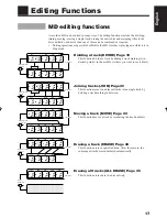
Page 22: ... be input using any of character types alphabets uppercase and lowercase symbols and numerals B C A A B A A C a b c A B C A a c A B C A a c b a c Dividing track A into 3 tracks Part to be erased Erasing track Joining tracks and Track No Track No Track No 1st 1st 1st 1st 2nd 2nd 2nd 3rd 2nd 3rd 3rd 3rd 4th 4th 5th RM SXM448E REMOTE CONTROL SPACE EDIT TITLE ENTER SET CANCEL SMALL LETTER 3 7 8 When u...

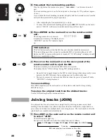
Page 23: ...keys on page 9 You can use or 1 to fast forward or reverse the track 4 Press SET when a point where you want to divide the track comes POSITION is displayed and the track marking fine adjustment display appears When the track has been divided as desired go to step 6 If the track has not been divided as desired fine adjust the track marking position Go to step 5 If you notice that the selected trac...

Page 24: ...trol unit to eject the MD The data in memory is written in the MD before it is ejected The display shows UTOCwriting during MD writing operation Be careful not to apply impact to the MD recorder during writing temporarily stored data into the MD Otherwise the recording may not be able to play later The data in memory is written in the MD also when the power is turned off while EDITING is being dis...

Page 25: ...e display shows TRACK PROTECTED one of the selected tracks has been protected against accidental erasure by another component You cannot edit such a protected track To cancel the editing press EDIT on the main unit or on the remote control unit 5 Press ENTER on the main unit or on the remote control unit The change made above is entered temporarily in memory The display shows EDITING and the TOC i...

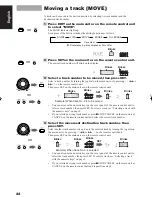
Page 26: ... unit or by pressing 4 or on the remote control unit Then press SET on the main unit or on the remote control unit You can also use the numeric keys on the cover panel of the remote control unit to select a track number then press SET To select a track see Selecting a track with the numeric keys on page 9 If you selected a wrong track number press 7STOP CANCEL on the main unit or CANCEL on the rem...

Page 27: ...ful not to apply impact to the MD recorder during writing temporarily stored data into the MD Otherwise the recording may not be able to play later The data in memory is written in the MD also when the power is turned off while EDITING is being displayed To cancel editing Press EDIT repeatedly on the main unit or on the remote control unit before pressing ENTER in step 5 Erasing a track ERASE A tr...

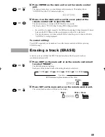
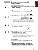
Page 28: ...r component You cannot edit such a protected track To cancel the editing press EDIT on the main unit or on the remote control unit 4 Press ENTER on the main unit or on the remote control unit The change made above is entered temporarily in memory The display shows EDITING and the TOC indicator lights up 5 Press 0 on the main unit or on the cover panel the remote control unit to eject the MD The da...

Page 29: ...ER on the main unit or on the remote control unit The change made above is entered temporarily in memory The display shows EDITING and the TOC indicator lights up 4 Press 0 on the main unit or on the cover panel of the remote control unit to eject the MD The data in memory is written in the MD before it is ejected The display shows UTOCwriting during MD writing operation Be careful not to apply im...

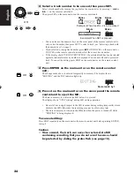
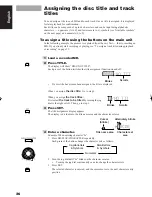
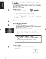
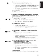
Page 30: ...k title during playback or recording on page 29 1 Load a recorded MD 2 Press TITLE The display will show DISC NO TITLE Each press of the button switches the title assignment function on and off If a disc title has already been assigned the title is displayed When you assign the disc title Go to step 3 When you assign the track titles First select the track to be titled by turning the jog dial to t...

Page 31: ... shows the disc title name and then shows the track number and the total playing time If the disc title is longer than 11 characters it scrolls on the display Note When using the TEXT COMPU LINK remote control system see page 31 titles will not be scrolled After editing the track title the name of the track is not displayed 6 Press 0 to eject the MD The data in memory is written in the MD before i...

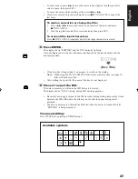
Page 32: ...er case Each press of SMALL LETTER switches the character case Lowercase letters can be input when the button is lit in green and uppercase letters can be input when the button is not lit 2 Input characters by using the character input keyboard The selected character is entered and the cursor moves to the next character entry position To move the cursor while entering a title press 4 or If you hav...

Page 33: ...tton MD recorder stops playing or recording and finishes the title assignment procedure at this point EDITING appears 3 Press ENTER on the main unit or on the remote control unit The display shows EDITING and the TOC indicator lights up Next the display shows the disc title name and then shows the track number and the total playing time If it is during playback the track will be played repeatedly ...

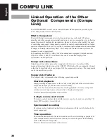
Page 34: ...ith this unit the cable with the monaural min plugs black connect the COMPU LINK jacks of the components Connect so that the Compu Link cables can bridge all of the components you have The components can be connected in any order Compu Link 3 features The Compu Link 3 system makes the following operations possible Shortcut playback Simply selecting an input source of the receiver starts playback o...

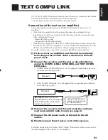
Page 35: ...n recording from the CD player To use this control system connect the receiver and this MD recorder as follows 1 If the receiver or amplifier and this unit have already been plugged into the AC outlets disconnect their AC power cords 2 Connect the receiver and this unit as described below using the COMPU LINK 3 SYNCHRO and TEXT COMPU LINK jacks 1 COMPU LINK 3 SYNCHRO jacks Use the supplied Compu L...

Page 36: ...bed below using the COMPU LINK 3 SYNCHRO and TEXT COMPU LINK jacks 1 COMPU LINK 3 SYNCHRO jacks Use the supplied Compu Link cable with the monaural mini plugs black 2 TEXT COMPU LINK jacks Use the supplied Text Compu Link cable with the stereo mini plugs green 3 Connect the CD player and this unit using the audio pin cord and a digital cable if any see page 6 4 Connect the AC power cord of the CD ...

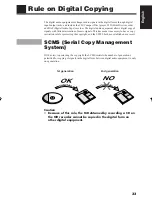
Page 37: ...ls This has made it necessary to have a copy restriction rule for protecting the copyright and the SCMS has been established as a result SCMS Serial Copy Management System With a view to protecting the copyright the SCMS restricts the number of generations permitted for copying of signals in the digital form between digital audio equipment to only one generation Caution Because of this rule the MD...

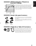
Page 38: ...s easy Two disc types The MD Mini Disc includes two disc types the recordable MD that can be recorded onto and the playback only MD that can exclusively be played back Although both types of discs are played in the same way that is by irradiating a laser beam on the disc and reading signals from the reflected light the ways they are recorded are completely different Playback only MD This type of d...

Page 39: ...ation during MD Mini Disc playback In case the optical laser cannot read disc signal due to vibration the actually reproduced audio is not interrupted because the data stored in the guard memory is available UTOC User Table Of Contents The recordable MD Mini Disc contains the recording of UTOC User Table Of Contents in addition to music data itself The UTOC includes the information on the position...

Page 40: ... a place subject to direct sunlight or where the temperature rises for example in a closed automobile The disc may be warped and unusable in these places In a bathroom or where the humidity is high The disc may be rusted in these places On a beach or sandbox The disc surface may be scratched or damaged if grit penetrates through an opening on the cartridge Periodical maintenance When the cartridge...

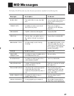
Page 41: ...a non recorded disc An attempt is made to join tracks that cannot be joined The MD is abnormal damaged The disc has no available space or the number of tracks has reached 254 An abnormality occurred during recording No MD is loaded An attempt is made to digitally dub a CD ROM Video CD etc An attempt is made to record on or edit a playback only MD The MD is protected against accidental erasure A tr...

Page 42: ...g recorded on the MD sounds will drop out while fast forwarding or reversing such an MD You cannot record on a blank portion of less than 2 seconds in the MD For this reason the actual recording time of discs may become shorter The MD records data in an original format that differs from that of conventional cassette tapes or DATs Since there are some limitations with this recording format the foll...

Page 43: ... not connected properly The power cord is unplugged from the power outlet A playback only MD is loaded The MD is protected against accidental erasure DISC PROTECTED is displayed in this case The batteries are exhausted The batteries are inserted with wrong polarity There is an obstacle between the remote control unit and remote control sensor The remote control sensor is under direct sunlight Cond...

Page 44: ...od Number of channels Frequency response S N ratio Dynamic range Wow flutter Input terminals Analog Digital Output terminal Analog Power requirements Power consumption Dimensions Mass Accessories Received optical ANALOG IN pin jack OPTICAL DIGITAL IN square optical connector jack Terminal name Reference input level Minimum input level ANALOG IN 275 mV rms 100 mV rms Terminal name signal wave lengt...

Page 45: ...J VC 0399JTMMDWJEM EN GE FR NL SP IT VICTOR COMPANY OF JAPAN LIMITED ...

Reviews: