


No. 51961
TM-H1950CG
19
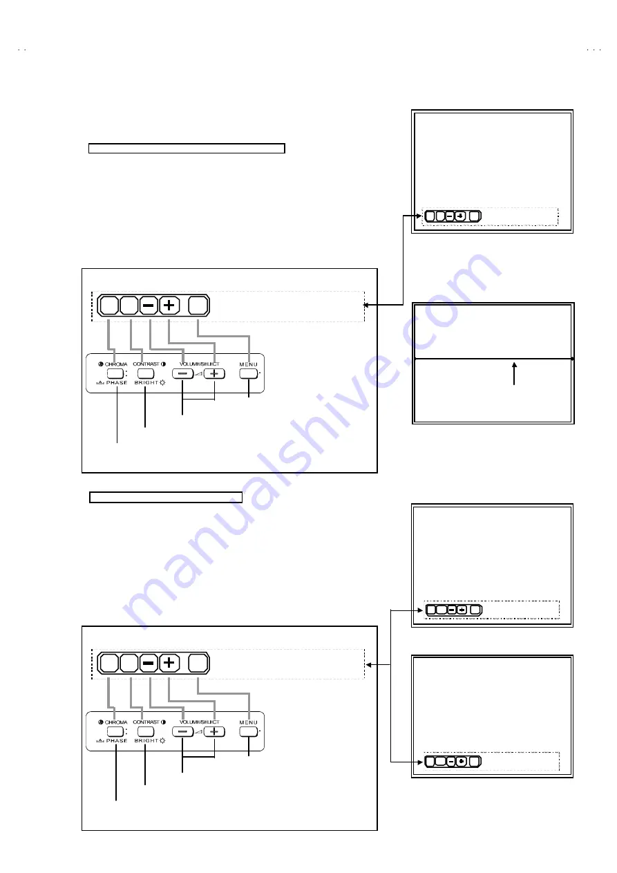
[ WHITE BALANCE Adjustment : METHOD 1 ]
Accordance with the screen display, select the each WHITE BALANCE mode
following below.
CUT OFF adjustment mode (Low light adjustment)
①
In the WHITE BALANCE menu screen, press the
CHROMA/PHASE
key to
enter to the CUTOFF adjustment mode (Fig. 9). In this case, key function is
replac ed as shown below.
②
Whenever press the
CHROMA/PHASE
key, change the adjustment c olour
of R, G and B.
③
The single horizontal line service screen appears if press the
CONT RAST/BRIGHT
key (Fig. 10).
Refer to the “Low-Light adjus tment” corresponding page about detailed
adjustment steps.
DRIVE adjustment mode (HIGH LIGHT)
①
In the WHITE BALANCE menu screen, press the
CONTRAST/BRIGHT
key to enter to the 6500 DRIVE adjustment mode (Fig. 11). In this c ase,
press the
VOL UME/SELECT (-)
key, enter to 9300 DRIVE mode.
②
Whenever press the
CHROMA/PHASE
key, change the “R DRIVE” or “B
DRIVE” adjustment mode.
③
CONT RAST/ BRIGHT
key is the switch of the screen display. If necessary,
you can shut off the display. Carefully, values of adjustment items are
changed while shut off the screen display.
Refer to the “High-Light adjustment” corresponding page about detailed
adjustment steps.
SINGLE HORIZONTAL LINE
Fig.10
Single horizontal line
RGB
EXIT
SERV
***
***
***
***
R CUTOFF :
Select the R, G or B mode
Display 1H line switch
Data operate (inc/dec) key
Adjustment mode exit key
<Function Display>
<Front Panel Key Arrangement>
CUTOFF ADJUSTMENT SCREEN
RG B
EXIT
SERV
***
***
***
***
R CUTOFF :
Fig.9
6500 R DRIVE :
RGB
EXIT
DISP
***
***
***
***
Select R or B mode
Display on/off switch
Data operate (inc/dec) key
Adjustment mode exit key
<Function Display>
<Front Panel Key Arrangement>
DRIVE 6500 ADJUSTMENT MODE
6500 R DRIVE :
RGB
EXIT
***
***
***
***
DISP
Fig.11
DRIVE 9300 ADJUSTMENT MODE
9300 R DRIVE :
***
***
***
***
RGB
EXIT
DISP
Fig.12