background image

Name of Parts (Continued)

Camera

.

.

D

E

F

G

A

B
C

H

A


Mounting Hole 

2

 2

(

A

 page 15)

B


Dome Cover

(

A

 page 13)

C


Inner Dome

(

A

 page 13)

D


Video Signal Output Connector (BNC)

(

A

 page 14)

E


Protection Cover

(

A

 page 14)

F


Power Supply Cable

(

A

 page 11)

G


Wiring Hole

(

A

 page 16)

H


Fall Prevention Wire Mounting Screw

(

A

 page 14)

Introduction

8

Summary of Contents for TK-C2201EEX

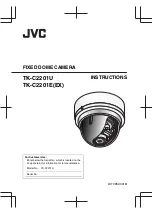
Page 1: ... DOME CAMERA TK C2201U TK C2201E EX INSTRUCTIONS For Customer Use Enter below the Serial No which is located on the body Retain this information for future reference Model No TK C2201U Serial No LST0952 001B ...

Page 2: ... Precautions 4 Name of Parts 6 Setup Setting the Switches 9 About Connection Cables 10 Installation Mounting the Camera 12 Adjustment Adjusting Image 17 Adjusting the Auto White Balance 22 Mounting the Dome Cover 23 Others Specifications 25 Introduction 2 ...

Page 3: ...symbols Note Indicates operating precautions Memo Indicates reference data regarding limitations on functions usage and the like A Indicates a reference page or item Contents of this manual Product names of other companies described in this manual are trademarks or registered trademarks of the respective companies Symbols such as and are omitted in this manual Design specifications and other conte...

Page 4: ... m Maintenance v Clean the dome cover lens using a lens wiper cloth or a tissue For tough stains wipe with a neutral detergent diluted with water followed by wiping with a dry cloth Do not use benzene or thinner to wipe the camera Doing so may melt the surface or cause it to fog m Energy Conservation v When the camera is not in use for a long time turn off the power for safety and energy conservat...

Page 5: ... of the automatic tracking white balance circuit This is not a malfunction v When this camera is used under high temperatures vertical stripes may appear on the screen This is a characteristic of the CCD and not a malfunction v When this camera is moved from a cold to warm place condensation may occur and the camera may not work In this case leave the camera under room temperature for about one ho...

Page 6: ...irectly to the ceiling or on the wall A page 13 step 2 to 3 on the removal methods C D E F A B G H J I SET MENU F ADJ N K L M A Focus Adjustment Ring A page 19 B Zoom Adjustment Ring A page 19 C Fall Prevention Sheet A page 13 D Rotation Knob A page 18 E MONITOR Terminal RCA pin A page 17 Introduction 6 ...

Page 7: ...ection Switches A page 9 L MENU Button Display the menu screen Refer to the attached manual MENU SETTING for more details about setting the menu M Status Indication Lamp Lights up when the power is turned on N J K H I SET Button This allows user to select menu screens and change or confirm settings Fine Focus Adjustment A page 20 Auto White Balance Adjustment A page 22 Introduction 7 ...

Page 8: ... Hole 2 2 A page 15 B Dome Cover A page 13 C Inner Dome A page 13 D Video Signal Output Connector BNC A page 14 E Protection Cover A page 14 F Power Supply Cable A page 11 G Wiring Hole A page 16 H Fall Prevention Wire Mounting Screw A page 14 Introduction 8 ...

Page 9: ...e switches to color when the subject is bright and black and white when it is dark The image is set to color at all times when OFF is selected Default setting AUTO 2 BLC OFF ON Backlight Compensation Selector Switch Set this to ON when shooting in backlight The subject becomes easier to see as brightness is adjusted according to the photometry area set in BLC AREA of the menu Default setting OFF M...

Page 10: ...the type of cable used v Be sure to turn off the power of devices before connecting cables To video Signal Cable To DC 12 V or AC 24 V Power Supply Video signal cable coaxial cable Connect a RG 59 75 K coaxial cable BNC to the video signal output connecter BNC Setup 10 ...

Page 11: ...ith low resistance or place the power supply near to the camera and shorten the length of the cable to restrict the voltage drop at the rated current of camera to below 10 If voltage drop occurs during operation the performance will be unstable v Do not connect the AC 24 V cable to commercial power supply If it is connected by mistake the internal circuit may be damaged Do not use the camera and m...

Page 12: ...eas If an embedded cover recessed bracket is required ensure it is securely mounted before installing the camera v Please refer to the instruction manual for the embedded cover recessed bracket in use for details on its installation v For details on the embedded cover recessed bracket please contact your JVC dealer Embedded Cover in Ceiling recessed bracket Ceiling Memo To mount the camera using a...

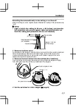
Page 13: ...ire not supplied 2 Remove the dome cover As illustrated in the diagram hold the dome cover such that the position alignment mark comes between the thumb and index finger and turn the cover in the counter clockwise direction to remove the cover Refer to page 24 for more details about position alignment mark 3 Remove the inner dome from the catches two locations The inner dome can be easily removed ...

Page 14: ...to cover the connectors This will isolate and protect the metallic parts of the connectors from the ceiling structures 3 Connect the power supply cable A page 11 4 Wrap insulation tapes around the connecting parts of the power supply cables Memo Wrapping insulation tapes will improve future work conditions as well as reduce penetration by noise and other objects 1 2 4 3 Fall prevention wire Solder...

Page 15: ...6 inch Do not use flathead screws Align the mark upwards when mounting the camera on the wall When using an impact screwdriver do not tighten the screws fully Tighten using your hand instead Failure to do so may damage the outer case Adjusting images After mounting is completed adjust the images while checking the actual image Adjusting Image A page 17 Installation 15 ...

Page 16: ...out opening any holes The basic mounting method is identical to steps in Mounting the camera directly to the ceiling or on the wall A page 13 1 Cut both ends of the extraction hole for the cable with a nipper and break off the excess material using tools such as long nose pliers 2 Pull out the cable from the extraction hole and mount it to the ceiling or wall Cable Installation 16 ...

Page 17: ...touching the metallic part of the monitor terminal before handling the camera as static electricity may cause the camera to malfunction 1 Mount the monitor Connect the monitor terminal of this camera to a test monitor to adjust the camera s shooting direction image and focus 2 Turn on the camera 75 Monitor terminal terminal Monitor Adjustment 17 ...

Page 18: ... Be sure to hold the rotation knob and adjust the rotation without holding the lens unit v Loosen the tilt fastening screw before performing tilt adjustment v After adjusting the field angle tighten and secure the tilt fastening screw so that the field angle will not be misaligned Note v Moving the camera beyond its adjustable range may deteriorate the performance of this camera v As this camera h...

Page 19: ...tch from point A to point B as illustrated in the diagram to disengage the gear Note To prevent the gear shaft from breaking when the gear is opened too far out from B remove the gear shaft from the bearing C in diagram In this case re insert the shaft back into the bearing C and return it to the original position before using Loosen the fastening screw for the focus adjustment ring and move the r...

Page 20: ... the focus adjust mode the electronic shutter will function automatically As a result the screen will appear grainy This is not a malfunction Shoot the subject Return the catch to A in the diagram and then rotate the knob to adjust the focus to the optimum position Rotate the focus adjust gear knob one base pitch in the direction of the arrow in the diagram to correct the focus shift when mounting...

Page 21: ... of the focus adjustment ring Hold and press the focus adjust gear between your fingers in the direction of the arrows in the diagram and tighten the fastening screw of the focus adjustment ring Focus adjustment ring Adjustment 21 ...

Page 22: ...C SET R GAIN B GAIN AWC OK WHITE BALANCE CONTROL E AWC SET R GAIN B GAIN 160 160 160 160 SET MENU F ADJ SET button MENU button button AWC OPERATION AWC OK adjustment completed during operation m Error display If auto white balance adjustment is not successful the following messages will appear on the monitor v AWC ERROR NG Subject error Displayed when there is not enough white color on the subject...

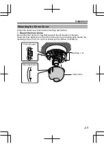
Page 23: ...ome Mount the inner dome in a way that supports the tilt direction of the lens Insert the inner depression of the inner dome into the protruding parts beside the fastening screw Push it in until it is locked by the catches 2 locations Inner dome Catches 2 Protruding part Inner depression Adjustment 23 ...

Page 24: ...ise dirction Memo Secure the dome cover with the two screws provided if necessary Note v When the cover is removed again after mounting the dome cover the field angle may changed If the field angle is changed re adjust the focus and the field angle v Check that the dome cover has been mounted firmly Incomplete mounting will cause the cover to drop down Position alignment mark Dome cover Dome cover...

Page 25: ... Equivalent to F 360 Angle of view f 2 8 mm 99 5 H 73 2 V f 10 5 mm 24 4 H 20 6 V Angle adjustment range Pan 175 Tilt 80 Rotation 100 Power supply AC 24 V 60 Hz DC 12 V TK C2201U AC 24 V 50 Hz 60 Hz DC 12 V TK C2201E Power current consumption 2 3 W TK C2201U 190 mA TK C2201E Mass 330 g Ambient temperature 10 f to 50 f 14 g to 122 g Operation 0 f to 40 f 32 g to 104 g Recommended Accessories TK C22...

Page 26: ...l Dimensions Unit mm inch 46 1 13 16 83 5 3 5 16 8 7 5 3 1 2 95 3 3 4 39 1 9 16 97 3 7 8 110 4 3 8 R 4 2 1 1 1 1 6 Specifications and appearance of this unit are subject to change for further improvements without prior notice Others 26 ...

Page 27: ...eiling Mounting Hole Unit mm inch 3 5 0 83 5 3 5 16 46 1 13 16 30 1 3 16 20 13 16 10 7 16 7 7 3 8 Screw Screw Front up Hole for cables Cable direction Camera Body Lens shooting range 1 1 0 4 3 8 Others 27 ...

Page 28: ...TK C2201U TK C2201E EX FIXED DOME CAMERA Q2012 JVC KENWOOD Corporation LST0952 001B ...

Reviews: