


16
1 2 : 3 0 : 4 5 3 H
1 1 – 6 – 9 8
3 H 1 2 : 3 0 : 4 5
1 1 – 6 – 9 8
1 2 : 3 0 : 4 5
3 H 1 1 – 6 – 9 8
1 2 : 3 0 : 4 5
1 1 – 6 – 9 8 3 H
4 MONITOR ON-SCREEN DISPLAY
Status information and other data including date/time, alarm input data, power loss (power failure) data and total operation
hours can be displayed on a connected monitor. Function settings can be switched via the on-screen function menu switches
and menu screens are also provided for timer recording program setting and date/time setting.
• Normally, the time/date data is shown on screen.
• Additional data displays and menu screens can be displayed by pressing the [MENU] button. This calls up the main menu
screen where you can select items as desired.
4-1 On-Screen Display in the Time/Date and Record Modes
Time/date and recording mode data is recorded and displayed on screen.
In the Stop, Record and Record Pause modes, data is superimposed on the input video signals.
• The on-screen display can switched ON/OFF using the <POSITION> switch in the function menu's ON SCREEN MODE
setting screen. You can also change the on-screen display position using this switch.
Menu switch
<POSITION> setting
Display
5
Connect the VCR's video output connector to the
monitor's video input connector.
1
Turn the power on (monitor and VCR) and engage the
Stop mode.
2
• When a video signal is input to the video input
connector, time/date, and recording mode are
superimposed on the picture.
• If there is no signal input, display data is
superimposed on a black background.
* If the date and time have not been set, correct date
and time indications are not available.
5
If no on-screen data is displayed, set the <POSITION>
menu switch in the function menu's ON SCREEN MODE
setting screen to the desired position (except "OFF").
5
Changing the display position
You can select the position on screen where data is
displayed with the <POSITION> menu switch in the ON
SCREEN MODE setting screen. Data can be displayed
in any one of the four corners of the screen.
Setting of the menu switch <POSITION>
– L-UP
: Left top (factory setting)
– R-UP
: Right top
– R-BOTTOM : Right bottom
– L-BOTTOM : Left bottom
– OFF
: Display is off. No indications are
shown.
●
For "Function menu switch setting", refer to page 19.
• In the Record mode, on-screen time/date and
recording mode data is recorded together with video
signals.
If you do not want to record on-screen data, set the
<POSITION> menu switch to "OFF".
• In the Play mode, on-screen data recorded on the tape
is displayed.
• "L-UP"
• "R-UP"
Minute
Hour
Recording mode
Month
Second
• "R-BOTTOM"
• "L-BOTTOM"
Day
Year (last two digits)
Recording mode
Recording mode
Recording mode
17
PAL
COUNT/
CLOCK
TIME
MODE
TIMER
REC
AL/PL
RESET
MENU
VIDEO CASSETTE RECORDER
SHIFT/TRACKING
SET/V.LOCK
RESET
/CANCEL
OPERATE
SR-L910E
OPE. LOCK
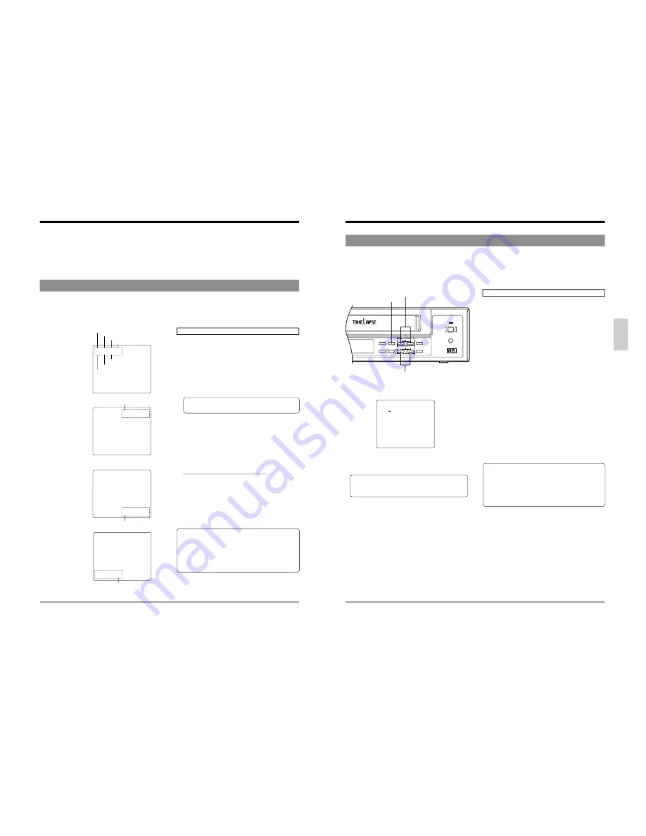
Operation
5
Connect the VCR's video output connector to the
monitor's video input connector.
1
Turn on the VCR and the monitor. Make sure the Stop
mode is engaged.
2
Press the [MENU] button.
[
The main menu screen is displayed.
3
Press the [SHIFT +/-] button to move the cursor arrow to
the item you want to display.
• Press the [SHIFT +] button to move the cursor arrow
down. Press the [SHIFT -] button to move it up.
4
Press the [SET +] or [SET -] button to display the
selected item.
5
To end menu operation and restore the normal screen,
press the [MENU] button.
•
When the [MENU] button is pressed during playback,
the monitor screen display switches from theplayback
picture to the input video signal (EE picture) and the
main menu is shown on the screen.
This means that even during playback you can check
menu contents. Press the [MENU] button again to
restore the playback picture.
4-2 Main Menu Display
You can display date and time data recorded when an alarm input or power failure occurs, as well as the hour meter (drum
rotating time) by selecting the desired item in the main menu.
The timer recording program setting screen, function menu switch setting screen, and date/time setting screen can also be
displayed by selecting the desired item in the main menu.
●
PROGRAM TIMER:
Displays the program setting screen for timer recording.
* Timer programming is not possible if the date and
time are not set. In this case, the date/time setting
screen will be displayed.
●
FUNCTION:
Displays the function menu setting screen.
●
ALARM IN:
Displays the date and time when an alarm signal was
input.
●
POWER LOSS
Displays the date and time when a power failure
occurred.
●
HOUR METER:
Displays the hour meter (drum rotating time).
●
CLOCK ADJUST:
Displays the date/time setting screen.
* Set the date and time before using this unit.
MAIN MENU
PROGRAM TIMER
FUNCTION
ALARM IN
POWER LOSS
HOUR METER
CLOCK ADJUST
PRESS (SHIFT, SET)
PRESS (MENU) TO END
4 MONITOR ON-SCREEN DISPLAY
[SHIFT +/–] buttons
[MENU] button
[SET +/–] buttons
Main menu screen