background image

22

Alarm/sensor

ALARM REC

[OFF]

recording mode

ON

setting

Turns the alarm recording function on or off.
Alarm recording is enabled only in the Timelapse Record mode.
An index code (VISS signal) is also recorded at the start point of alarm
recording as an alarm cue signal.
OFF : Alarm recording is disabled.

ON

: This unit enters the VHS SP Record mode,


when an alarm signal is input

to the rear panel's [ALARM IN] terminal during timelapse recording.

5-2 Contents of the Function Menu Switches

5  SETTING OF THE FUNCTION MENU SWITCHES

Function

Screens

Items

Set values

[    ]: Factory setting

SENSOR REC

[OFF]
ON

Selects the recording duration for alarm recording or sensor recording.
5 ..... 180 : Alarm or sensor recording is performed for the time specified (5 sec.

to 180 sec.).

TAPE END: Alarm or sensor recording continues until the tape ends.
MANUAL : Alarm or sensor recording continues for as long as alarm signals

are input.
Set to this position when specifying the alarm recording time with a
switcher.

DURATION

5
15
30
60
120
[180]
TAPE END
MANUAL

Turns the sensor recording function on or off.  Sensor recording is enabled in
the Stop mode. An index code (VISS signal) is also recorded at the start point of
sensor recording.
OFF : Sensor recording is disabled.
ON

: When an alarm signal is input to the rear panel's [ALARM IN] terminal in

the Stop mode. this unit automatically starts recording in the VHS SP
Record mode.

Selects whether or not the alarm buzzer sounds during alarm or sensor
recording.
OFF : The buzzer does not sound.
ON

: The buzzer sounds.

TAPE END

[STOP]

MODE

REW
REPEAT
EJECT

BUZZER

[OFF]
ON

Set the operation mode at tape end during recording in the case when alarm or

sensor recording is executed even once.
STOP

: Stops at tape end.

REW

: Rewinds the tape automatically and stops.

REPEAT : Rewinds the tape automatically to the beginning and restarts

recording.

EJECT

: The tape is ejected.

Select the RS-232C data transfer speed from 1200 bps, 2400 bps, 4800 bps or
9600 bps.

RS-232C
parameter
setting

BAUD RATE

1200
2400
4800
[9600]

This screen is displayed on the on-screen setting screen only when the (optional) RS-232C board
SA-K97U is installed.

VTR mode 2

CAMERA SW

[OFF]

setting

1 FIELD

1 FRAME

Sets the camera switching interval for output to an external sequential switcher
during recording.
OFF

: No camera switching signal is output.

1 FIELD : Set to this position to switch the camera every 1 field.
1 FRAME : Set to this position to switch cameras every 1 frame.

CAM SW

[5 msec]

WIDTH

20 msec

Sets the output time of the camera switching signal.
5m sec : Camera switching signal output time for 3/12/24H recording : 5 msec.
20m sec : Camera switching signal output time for 3H recording : 5 msec.

12/24H recording : 20 msec.

TIMER ALARM

OFF
[ON]

Sets whether or not the alarm signal input should be enabled during timer
recording.
OFF : Alarm signal input during timer recording is disabled.
ON

: Alarm signal input during timer recording is enabled.

23

PAL

6  PREPARATION

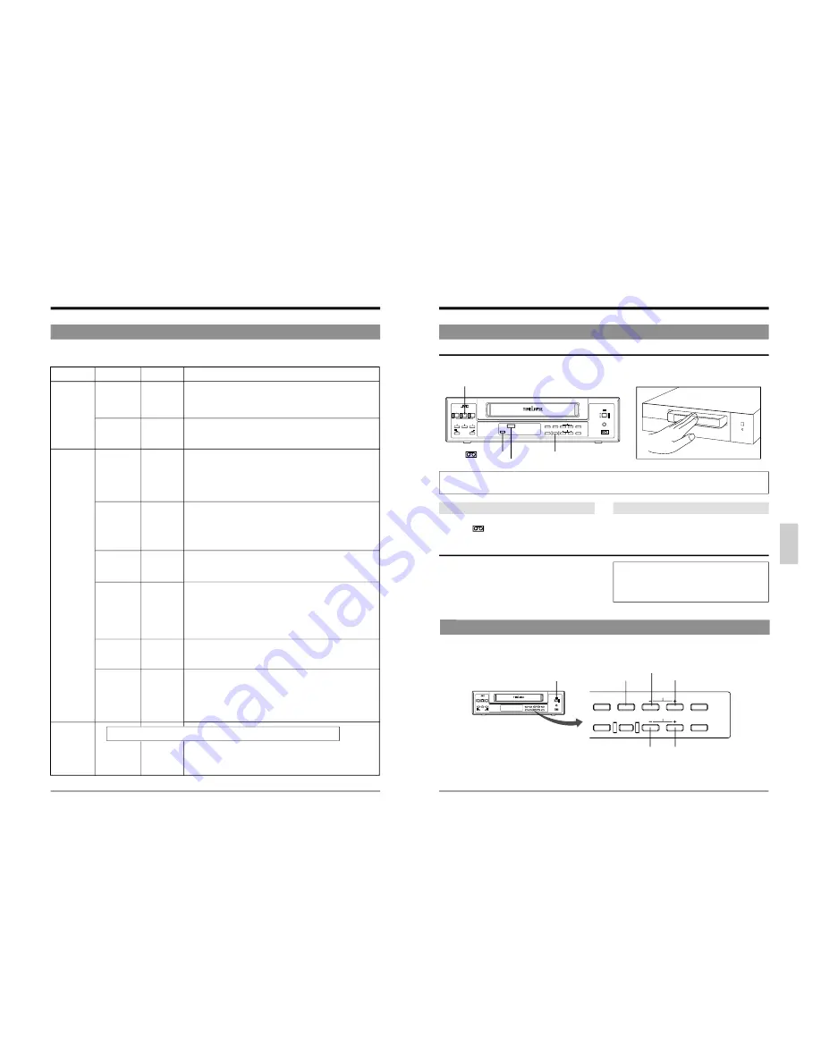
6-2  Date and Time Setting

• Time-keeping continues even when the power cable is unplugged from the AC outlet or a power failure occurs.
• If the power cable has been unplugged for a long time of period, check the current time before using the VCR.  (Time shift

may occur under certain operating or environmental conditions.)

[SHIFT +] button

[MENU] button

6-1  Cassette Loading/Unloading

Loading

Insert the cassette with its label side facing you.
Gently push the center of the cassette until the machine starts automatic loading.

[EJECT] button

 ) indication

TIMER indication

[TIMER REC] button

Note:

To avoid damage or injury, do not insert your hand or other foreign objects into the cassette loading slot.

Auto power on

When a cassette is loaded, the power automatically turns
on and the ( 

 ) cassette indication appears.

Auto play

When a cassette with no erasure prevention tab is loaded,
playback starts automatically.

Unloading

5

Press the [EJECT] button.

[

The cassette is ejected.

If the power is not on when the [EJECT] button is
pressed, power is automatically switched on and the
cassette is ejected. Once the cassette is unloaded, the
power turns off again automatically.

If the Timer Recording Standby mode is engaged (TIMER
indication is shown on the display), the cassette will not be
ejected when the [EJECT] button is pressed.
To unload the cassette, press the [TIMER REC] button to
release the Timer Recording Standby mode, then press the
[EJECT] button.

The time/date generator and timer recording will not function if the date and time are not set.
The time/date setting can be enabled on the CLOCK ADJUST menu screen or the front panel display.

[SHIFT –] button

COUNT/

CLOCK

TIME

MODE

TIMER

REC

AL/PL

RESET

MENU

SHIFT/TRACKING

SET/V.LOCK

RESET

/CANCEL

PAL

[SET –] button

[SET +] button

[OPERATE] button

Summary of Contents for SR-L910E

Page 1: ...the best possible performance PAL PAL A INTRODUCTION CONTROLS AND CONNECTORS PREPARATION RECORDING PLAYBACK AND SPECIAL EFFECTS PLAYBACK TROUBLE SHOOTING CONNECTIONS MONITOR ON SCREEN DISPLAY SETTING OF THE FUNCTION MENU SWITCHES APPENDIXES OPTIONAL SA K97U RS 232C INTERFACE BOARD R VICTOR COMPANY OF JAPAN LIMITED Printed in Thailand 2001 VICTOR COMPANY OF JAPAN LIMITED SR L910E EK VIDEO CASSETTE ...

Page 2: ...ble shock hazard by inadvertent connection to the mains supply If this product is not supplied fitted with a mains plug then follow the instructions given below DO NOT make any connection to the Larger Terminal coded E or Green Thewiresinthemainsleadarecoloured inaccordance with the following code Blue to N Neutral or Black Brown to L Live or Red If these colours do not correspond with the termina...

Page 3: ...vation Signal 38 7 9 How to Restore Recording After Power Failure 39 7 10 External Timer Recording 39 7 11 Tape End Buzzer 39 8 PLAYBACK AND SPECIAL EFFECTS PLAYBACK 8 1 Preparation 40 8 2 Playback 40 8 3 Special Effects Playback 41 8 4 Index Search 42 8 5 Tracking V Lock Adjustment 42 9 TROUBLESHOOTING 9 1 Error Indication 43 9 2 No Error Indication 44 10 OPTIONAL SA K97U RS 232C INTERFACE BOARD ...

Page 4: ...s few as 5 or 6 months Therefore it is important that the total hours of operation be carefully monitored An hour meter in the on screen display see page 18 shows the accumulated time In the chart below the hours accumulated in each month are shown in relation to the number of hours used per day Times shown inside shaded area indicate that maintenance should be performed Check or replace the follo...

Page 5: ... to be recorded during alarm signal input or every hour exact hour with no minute and second using the function menu switch INDEX ALARM SKIP REW button Rewinds the tape Starts reverse shuttle search when pressed in the Play mode If the function menu switch INDEX SEARCH is set to ON and an index recorded tape is loaded Index alarm Search starts in the reverse direction when this button is pressed i...

Page 6: ...ng the index search by FF REW Button the index number indicates 01 and 00 only 11 CAM SW OUT ALARM IN COM COM ALARM REC OUT SERIES CLOCK ALARM RESET TAPE END OUT WARNING REC OUT IN OUT 8 7 1 2 3 4 6 5 VIDEO AUDIO IN IN OUT OUT REMOTE MIC IN CAM SW OUT ALARM IN COM COM ALARM REC OUT SERIES CLOCK ALARM RESET TAPE END OUT WARNING REC OUT IN OUT 2 1 FRONT PANEL 2 3 Rear Panel 2 CONTROLS AND CONNECTORS...

Page 7: ... starts automatically VCR activation signal input When the TERMINAL SEL 1 menu switch is set to EXT recording start and stop can be controlled with external signal input Connect to an external control device When a VCR activation signal ground input is received recording starts automatically and continues for as long as the VCR activation signals are input Clock reset signal input When the TERMINA...

Page 8: ...ting the Rear Panel Input Output Terminal Connections CAM SW OUT camera switching signal output terminal ALARM IN alarm signal input terminal ALARM RESET alarm reset terminal ALARM REC OUT alarm recording mode signal output terminal TAPE END OUT tape end output terminal WARNING REC OUT warning signal recording mode signal output terminal ALARM COM IN Sequential switcher alarm output terminal COM C...

Page 9: ...ta is recorded together with video signals If you do not want to record on screen data set the POSITION menu switch to OFF In the Play mode on screen data recorded on the tape is displayed L UP R UP Minute Hour Recording mode Month Second R BOTTOM L BOTTOM Day Year last two digits Recording mode Recording mode Recording mode 17 PAL COUNT CLOCK TIME MODE TIMER REC AL PL RESET MENU VIDEO CASSETTE RE...

Page 10: ...O REC OFF REC CHECK MANUAL TAPE END MODE REPEAT INDEX SEARCH OFF INDEX AL SKIP ALARM TAPE END BUZZER OFF WARNING BUZZER OFF PRESS SHIFT SET PRESS MENU TO END VTR MODE 2 SUMMER TIME OFF TAERMINAL SEL 1 SERIES TAERMINAL SEL 2 WARN REC REMAIN OFF NOISELESS PLAY OFF CAMERA SW OFF CAM SW WIDTH 5msec PRESS SHIFT SET PRESS MENU TO END 5 SETTING OF THE FUNCTION MENU SWITCHES You can customize the VCR s fu...

Page 11: ... operation mode at tape end during recording in the case when alarm or sensor recording is executed even once can be set with the menu switch TAPE END MODE on the alarm sensor recording mode setting screen 21 5 2 Contents of the Function Menu Switches 5 SETTING OF THE FUNCTION MENU SWITCHES Factory setting Function Screens Items Set values VTR mode 2 SUMMER TIME OFF setting ON Turns summer time co...

Page 12: ... switcher during recording OFF No camera switching signal is output 1 FIELD Set to this position to switch the camera every 1 field 1 FRAME Set to this position to switch cameras every 1 frame CAM SW 5 msec WIDTH 20 msec Sets the output time of the camera switching signal 5m sec Camera switching signal output time for 3 12 24H recording 5 msec 20m sec Camera switching signal output time for 3H rec...

Page 13: ...e built in battery Set the date and time on the front panel display MONTH DAY HOUR MINUTE YEAR 25 PAL During daylight savings time 1 Set the time with one hour delay 2 After setting the time set the SUMMER TIME switch to ON The set time advances one hour 3 At the end of the daylight savings time season set the SUMMER TIME switch to OFF The standard time instead of Summer Time is displayed Set whet...

Page 14: ...ies recording Tape end buzzer End indication in the counter display 5 CAMERA SW Factory setting OFF Sets the switching timing for cameras connected to an external sequential switcher To switch cameras after each field or frame set this menu switch to FIELD or FRAME 5 CAM SW WIDTH Factory setting 5 msec Sets the output time for the camera switching signal to be output to the external sequential swi...

Page 15: ...PRESS MENU TO END PROGRAM TIMER DAILY S T A R T E N D MODE 1 H 2 H 3 H 4 H 5 H 6 H 7 H 8 H PRESS SHIFT SET RESET PRESS MENU TO END PROGRAM TIMER DAILY S T A R T E N D MODE 1 3 0 6 8 3 0 1 7 1 5 3 H 2 H 3 H 4 H 5 H 6 H 7 H 8 H PRESS SHIFT SET RESET PRESS MENU TO END PROGRAM TIMER DAILY S T A R T E N D MODE 1 3 0 6 8 3 0 1 7 1 5 3 H 2 1 7 1 0 0 0 2 2 0 0 2 4 H 3 H 4 H 5 H 6 H 7 H 8 H PRESS SHIFT SET...

Page 16: ... Stop time minute and Record mode with the SHIFT and SET buttons When all values are set the set program No is shown on the VCR s display 5 Accessing another day of the week Select the Record mode so that it is blinking and press the SHIFT button Or select Start time so that it is blinking and press the SHIFT button The blinking part stops blinking You may now select another day of the week 6 To s...

Page 17: ...ogrammed start time If no cassette is loaded The TIMER and indications blink Load a cassette with safety tab in place Cassettes with no tab are ejected When the TAPE END MODE function menu switch is set to STOP REW or EJECT and the tape ends during timer recording The cassette is ejected Recording will start again when a cassette with safety tab in place is loaded 33 PAL AL TIME MODE Extinguished ...

Page 18: ...RM ON DURATION 180SEC BUZZER OFF TAPE END MODE STOP PRESS SHIFT SET PRESS MENU TO END 7 RECORDING 7 5 Sensor Recording Sensor recording is executed only when the VCR is in the Stop mode Stop or Timer Record Standby mode and an alarm signal is input to the rear panel s ALARM IN terminal Perform the settings for sensor recording in the same way as for Alarm Recording on page 33 The mechanism of the ...

Page 19: ...ed SR L910E EKs As soon as the tape ends in one VCR the next VCR in the series starts recording 7 RECORDING 5 Connect the first VCR s SERIES CLOCK OUT terminal to the second VCR s SERIES CLOCK IN terminal Connect the second VCR s SERIES CLOCK OUT terminal to the third VCR s SERIES CLOCK IN terminal Repeat for all connected VCRs Connect the VCR s COM terminals as well 5 Connect a video camera and o...

Page 20: ...G BUZZER OFF PRESS SHIFT SET PRESS MENU TO END VTR MODE 1 SHARPNESS NORMAL VIDEO MODE AUTO AUTO REC ON REC CHECK MANUAL TAPE END MODE REPEAT INDEX SEARCH OFF INDEX AL SKIP ALARM TAPE END BUZZER OFF WARNING BUZZER OFF PRESS SHIFT SET PRESS MENU TO END 7 9 How to Restore Recording After Power Failure 7 RECORDING If a power failure occurs during recording recording will restart in the same mode as so...

Page 21: ...ack When the MENU button is pressed during playback the monitor screen display switches from the playback picture to the input video signal EE picture and the main menu is shown on the screen This means that even during playback you can check menu contents Press the MENU button again to restore the playback picture 41 PAL 8 PLAYBACK AND SPECIAL EFFECTS PLAYBACK Shuttle search reverse and fast forw...

Page 22: ...with cassette loading unloading or mechanism operation 5 When a problem occurs the error indication E blinks 5 When any one of the error indications is shown a 12 V warning signal is output from the rear panel s WARNING OUT connector for E 01 to E07 and E 11 during recording only when the TERMINAL SEL 2 menu function switch is set to WARN 5 When the function menu switch WARNING BUZZER is set to ON...

Page 23: ...een removed q Is the clock set correctly Is the timer properly programmed q Is the TIMER indication lit Is the TIMER indication lit This is normal q Is the clock set q Is the POSITION function menu switch set to OFF Is the function menu switch TAPE END MODE in the alarm sensor recording mode setting screen set to STOP EJECT or REW If so when the tape ends during recording in the case when alarm re...

Page 24: ...VC SENSE TABLE1 OFF 8 Data 8 9 Data 9 A ACK PLAY REV REC REC PLAY REQUEST B NAK FF REC VTR INQ PAUSE C REW D F FIELD STEP E F STOP STILL 10 3 SA K97U RS 232C Protocol Commands RS 232C protocol JVC base table JVC table 1 10 OPTIONAL SA K97U RS 232C INTERFACE BOARD 0 1 2 3 4 5 6 7 8 9 A B C D E F 0 Data 0 ENTER TIMER ON SCREEN VISS FRAME CODE ON ON FWD COUNT 1 COMPLE Data 1 CLEAR TIMER ON SCREEN VIS...

Page 25: ... s 2 byte numeric data should be input after transmission of this command Eg To search for the 3rd alarm input point from the current position The VCR starts INDEX search after returning ACK When the specified point is reached the VCR returns COMPLETION 01H If the end or beginning of the tape is reached before the specified point the VCR returns NOT TARGET 05H Sending either the 30H 30H or 30H 31H...

Page 26: ...hour minute and second as 6 bytes Each byte has a value of 30H to 39H 30H corresponds to 0 and 39H to 9 Example For 15 30 45 the VCR returns 31H 35H 33H 30H 34H and 35H 3 COUNT CODE D0H VCR returns the counter data beginning with the 4th digit from the right in 4 bytes ASCII codes 30H 39H correspond with the numbers 0 9 eg 1234 31H 32H 33H 34H 4 DEVICE TYPE D1H VCR returns the last 4 characters of...

Page 27: ...showing the warning status In this case release the warning via the RS 232C with the CLEAR 56H To release it on the VCR turn the OPERATE button off and on again 10 ALARM INPUT 06H SR L910E EK return code This is returned when an alarm signal is input during recording 53 10 OPTIONAL SA K97U RS 232C INTERFACE BOARD 2 4 Others Input data correction Error cancellation These are return codes from the S...

Page 28: ...5 Recording system 5 Signal system 5 Tape speed 5 Recording and playback time 5 Fast forward rewind time 5 Power supply 5 Power consumption 5 Dimensions 5 Weight 5 Operating temperature 5 Operating humidity 5 Storage temperature Video System 5 Signal input 5 Signal output 5 Horizontal resolution 5 Video S N Audio system 5 Number of tracks 5 Line input 5 Mic input 5 Line output 5 Frequency response...

Reviews: