


1-8 (No.MB338)
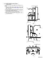
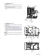
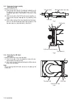
3.1.2 Removing the side panels (L)/(R)
(See Fig.3)
• Remove the rear cover.
(1) From the bottom side of the main body, remove the two
screws
C
attaching the side panels (L)/(R).
(2) Slide the side panels (L)/(R) in the direction of the arrow
and remove the side panels (L)/(R).
Fig.3
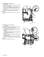
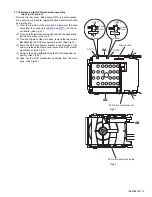
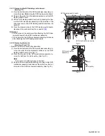
3.1.3 Removing the top cover assembly
(See Figs.4 and 5)
• Remove the rear cover and side panels(L)/(R).
(1) From the left side of the main body, disconnect the card
wires from the connectors (
CN703
,
CN709
) on the micon
board. (See Fig.4.)
(2) Remove the screw
D
attaching the top cover assembly.
(See Fig.4.)
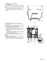
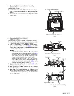
(3) From the right side of the main body, disconnect the card
wire from the connector
CN105
on the main board. (See
Fig.5.)
(4) Disconnect the wire from the connector
CN108
on the main
board. (See Fig.5.)
Reference:
When connecting the wire, pass it through the slot
b
of
the main board as before. (See Fig.5.)
(5) From the both sides of the main body, remove the two
screws
E
and screw
F
attaching the top cover assembly.
(See Figs.4 and 5.)
(6) Release the joints
a
and remove the top cover assembly.
(See Figs.4 and 5.)
Fig.4
Fig.5
Side panel(R)
Side panel(R)
C
C
E
D
Micon board
CN703
CN709
Top cover assembly
a
E
Main board
a
CN108 CN105
Top cover assembly
b
F
Summary of Contents for SP-UXQD9S
Page 32: ...1 32 No MB338 SECTION 5 TROUBLESHOOTING This service manual does not describe TROUBLESHOOTING ...
Page 33: ... No MB338 1 33 ...
Page 41: ...2 5 SHEET 4 ...
Page 71: ...3 21 MEMO ...


