RV-B550BU
1-22
35
36
34
33
32
31
30
29
28
27
26
25
24
23
22
21
20
19
18
17
16
15
14
13
12
11
10
9
8
7
6
5
4
3
2
1
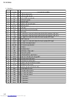
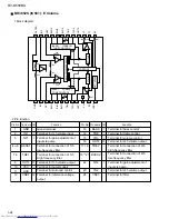
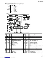
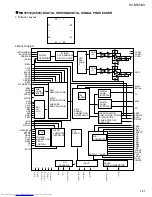
3. Functions
PD AC
FBAL
TBAL
PDFR
PDER
PDE
PD BD
TE BPF
VDET
CROSS
TE OUT
TE-
FE OUT
FE-
/NRFDET
GND
LD OFF
VREF
ENV
OFTR
C.AGC
ARF
C.ENV
C.EA
CS BDO
BDO
CS BRT
LD
LD ON
LDP
VCC
RF-
RF OUT
RF IN
PD
Pin No.
Symbol
I/O
I
O
I
--
--
I
O
I
I/O
O
I/O
I/O
I/O
O
I/O
O
O
--
O
O
--
O
I
O
O
I
O
I
I
I
I/O
I/O
I
I
I
I
I-V amp input
I-V amp input
I-V amp input
I-V amp input
E I-V amp gain control
F I-V amp gain control
Tracking balance control
Focus balance control
Inverse input pin for focus error amp
Output pin of focus error
Inverse input pin for tracking error amp
Tracking error signal output
Tracking error cross output
Input pin of tracking error through BPF
Vibration detection signal output
Connect to ground
Reference voltage output
Functions and operations
APC amp input terminal
APC amp output terminal
APC ON/OFF control terminal
Envelope output
Ground
RF detection signal output
Of-track status signal output
BDO output pin
A capacitor is connected to this terminal to detect the envelope of RF signal
RF output
Connecting pin of AGC loop filter
RF input
RFamp output
Inverse input pin for RF amp
Power supply
Connect to ground
A capacitor is connected to this terminal to detect the envelope of RF signal
A capacitor is connected to detect the lower envelope of RF signal
A capacitor is connected to detect the lower envelope of RF signal

