RC-BM5
1-7
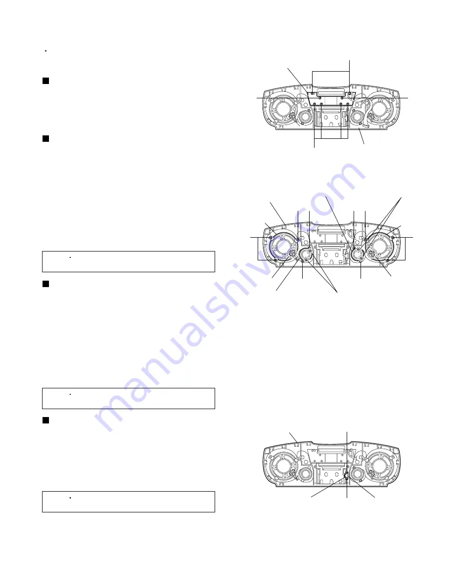
Fig.6
Display board
Front cabinet assembly
C
C
C
C
Fig.7
Front cabinet
assembly
Soldered sections
d
Soldered
section
b
Soldered sections
e
Soldered
section
c
Right main
speaker
Right sub speaker
Left main
speaker
Left sub speaker
D
D
D
D
E
E
E
E
Fig.8
Front cabinet assembly
Cassette door damper
Bracket
F
F
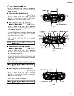
Removing the display board
(See Fig. 6.)
From the inside of the front cabinet assembly,
remove the eight screws
C
retaining the display
board and then take out the display board.
<Front cabinet section>
Prior to performing the following procedures,
remove the front cabinet assembly from the rear
cabinet assembly.
Removing the right and left main
speaker assemblies
(See Fig. 7.)
1.
2.
3.
From the inside of the front cabinet assembly,
remove the six screws
D
retaining the right and left
main speaker assemblies.
Remove the solders from the soldered sections
b
and
c
of the right and left main speaker
assemblies, remove the wires.
Take out the right and left main speaker
assemblies.
Removing the right and left sub
speaker assemblies
(See Fig. 7.)
1.
2.
3.
From the inside of the front cabinet assembly,
remove the four screws
E
retaining the right and
left sub speaker assemblies.
Remove the solders from the soldered sections
d
and
e
of the right and left sub speaker assemblies,
remove the wires.
Take out the right and left sub speaker assemblies.
Removing the cassette door damper
(See Fig. 8.)
1.
2.
From the inside of the front cabinet assembly,
remove the two screws
F
retaining the bracket of
the cassette door damper.
Take out the cassette door damper.
[Note]
After assembly, apply a locking agent to
the screws F.
[Note]
After assembly, apply a locking agent to
the screws D.
[Note]
After assembly, apply a locking agent to
the screws E.
Summary of Contents for RC-BM5
Page 41: ...RC BM5 2 1 A B C D E F G 1 2 3 4 5 Block diagram ...
Page 48: ...RC BM5 2 8 RC BM5 H A B C D E F G 1 2 3 4 5 Printed circuit boards Main board Reverse side ...
Page 49: ...RC BM5 2 9 A B C 1 2 3 4 5 Tuner board Cassette board Reverse side Reverse side ...
Page 50: ...RC BM5 2 10 A B C D 1 2 3 4 5 Display board Reverse side Power amplifier board Reverse side ...
Page 51: ...RC BM5 2 11 A B C 1 2 3 4 5 Volume switch board Reverse side Phone jack board Reverse side ...

